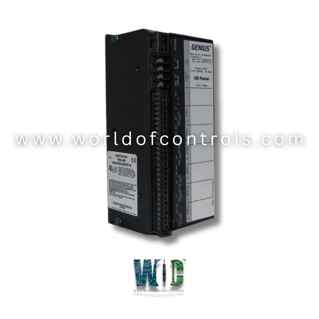
World Of Controls understands the criticality of your requirement and works towards reducing the lead time as much as possible.
IC660BBA101K - Input Block is available in stock which ships the same day.
IC660BBA101K - Input Block comes in UNUSED as well as REBUILT condition.
To avail our best deals for IC660BBA101K - Input Block, contact us and we will get back to you within 24 hours.
Part No.: IC660BBA101K
Manufacturer: General Electric
Country of Manufacture: United States of America (USA)
Rated Voltage: 115 VAC / 125 VDC
No.of of Points: 6
Inputs: Platinum, Nickel or Copper RTDs
Calibration: Factory
Operating Voltage: 93-132 VAC / 105-145 VDC
Points per Common: 3 groups of 2
Product Type: Input Block
Availability: In Stock
Series: VersaMax
IC660BBA101K is an Input Block developed by GE. It is part of the VersaMax series. Designed for industrial applications requiring accurate temperature monitoring, it is a component of the Genius I/O Series by GE Fanuc. This module operates at a rated voltage of 115 VAC or 125 VDC, offering flexibility in different power environments.
Specifically built to monitor temperature inputs from Resistive Temperature Detectors (RTDs). It is capable of detecting temperature variations as small as one-tenth of a degree, making it ideal for precision monitoring. There are two similar models in this RTD input block range: the IC660BBA101 (115 VAC/125 VDC) and the IC660BBA124 (48 VDC), with the only difference being their input power requirements.
This block includes six RTD-compatible inputs, organized in three isolated and independent sets of two inputs each. These fully isolated circuits allow users to connect RTDs made from platinum, copper, or nickel, providing versatility across a wide range of temperature-sensing applications. The independent input sets enhance reliability and reduce interference between channels.
Self-regulating design. An integrated multiplexer is responsible for switching the A/D converter between active RTD inputs and internal reference resistors. The block supports a resistance range of 0 to 5,000 ohms, allowing it to interpret signals from a wide variety of RTD types with accuracy.
The module can be configured to process data in Celsius, Fahrenheit, ohms, or counts, depending on user preferences. For setup and control, the IC66HHM501D handheld monitor is recommended and fully compatible. This handheld monitor not only aids in configuration but also enables users to view real-time data and diagnostics directly on-site.
Users can configure a range of input parameters including input filter time, RTD resistance, linearization, alpha-type selection, and alarm thresholds. These settings enhance the flexibility and accuracy of temperature measurements. Importantly, recalibration is not required, as the module comes factory-calibrated for long-term use.
Includes built-in automatic diagnostic features. It performs circuit diagnostics to identify issues such as open wires, internal faults, input short detection, and wiring errors. These diagnostics are reported to both the handheld monitor and the CPU, depending on user configuration. Fault reporting can be enabled or disabled circuit by circuit, providing granular control over system monitoring.
While most fault conditions do not interrupt block functions and do not require manual intervention, High or Low Input Alarm faults must be cleared before detection can restart. The system ensures that faults are flagged immediately, allowing users to take corrective action when necessary without impacting overall block performance.
The WOC team is always available to help you with your Mark I and II requirements. For more information, please contact WOC.
What is IC660BBA101K?
It is an Input Block developed by GE under VersaMax series.
What happens when a shorted input is detected?
When a shorted input is detected, it indicates that the RTD input is electrically shorted, which prevents accurate resistance measurement and temperature readings. This could be due to faulty wiring or a malfunctioning RTD sensor. The block flags this fault, and the wiring or sensor needs to be inspected and fixed.
How can I fix a Wiring Error fault?
A Wiring Error fault occurs when the connections between the RTD and the block's Terminal Assembly are incorrect. To resolve this, refer to the wiring diagram on the block’s faceplate and ensure that the wiring is correctly configured according to the specifications.
What does the Open Wire diagnostic indicate?
The Open Wire diagnostic occurs when there is insufficient current flow through the RTD input circuit, typically because the RTD is disconnected, faulty, or missing. This alert helps prevent inaccurate readings by notifying you of broken or missing connections.
What is the Overrange diagnostic, and how does it work?
The Overrange diagnostic is triggered when the input temperature exceeds the maximum allowed value for the connected RTD. The acceptable upper limits depend on the type of RTD in use (e.g., platinum, nickel). When Overrange occurs, the block reports this fault and may substitute a predefined maximum value for the input temperature reading.
What causes the Underrange diagnostic?
The Underrange diagnostic is triggered when the input temperature falls below the minimum supported value for the RTD. This can indicate a fault in the RTD or wiring. Instead of reporting the actual temperature value, the block uses a predefined Underrange value to represent the fault.