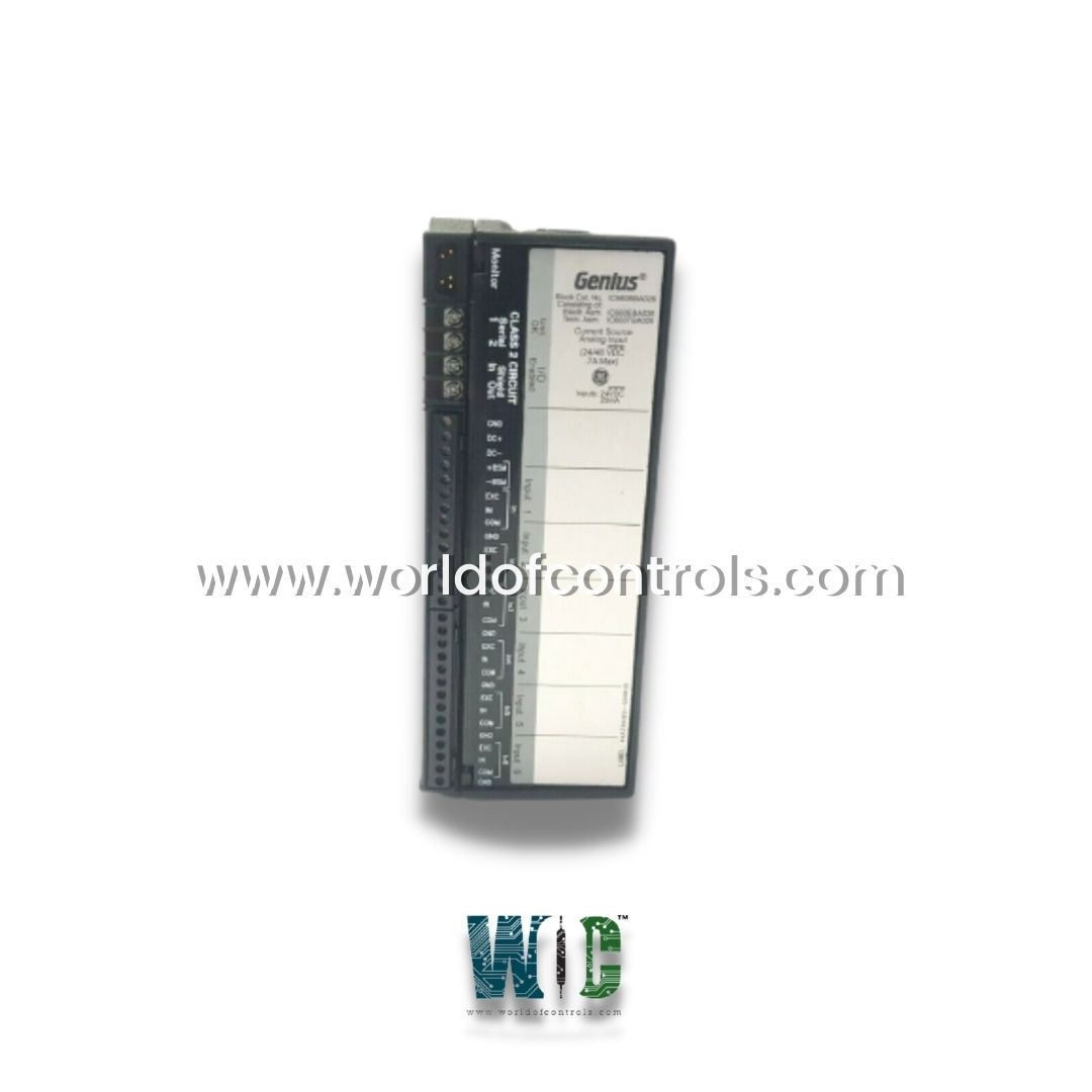
World Of Controls understands the criticality of your requirement and works towards reducing the lead time as much as possible.
IC660BBA026K - 24/48V DC Analog Input/Output Module is available in stock which ships the same day.
IC660BBA026K - 24/48V DC Analog Input/Output Module comes in UNUSED as well as REBUILT condition.
To avail our best deals for IC660BBA026K - 24/48V DC Analog Input/Output Module, contact us and we will get back to you within 24 hours.
SPECIFICATIONS:
Part Number: IC660BBA026K
Manufacturer: General Electric
Series: Versamax
Brand: GE Fanuc
Series: Genius I/O
Product Description: 24/48V DC Analog Input/Output Module
Points per common: One group of 6
Block Power: 115V AC/ 125V DC
Output Signals: 4-20 mA
Communication protocol: Genius Protocol
Heat Dissipation: 12 Watts
Status LEDs: Unit OK, I/O Enabled
Block-to-Block Isolation: 1500 Volts
Block to Block Isolation: 1500V for one minute
Input conversion time: 16.6ms to 400ms
Accuracy: 0.1% of full-scale reading
Input Resolution: 1 microamp
Group to Group Isolation: 1500 V RMS
Supply voltage range: 18-56 VDC
Input Accuracy: 0.1% of the full-scale reading
Size (HxWxD): 8.83 x 3.34 x 3.91 inches
Product Type: Availability: In Stock
Weight: 1.5 Kg
Country of Origin: United States
Manual: GFK-0691D
FUNCTIONAL DESCRIPTION:
IC660BBA026K is a 24/48V DC Analog Input/Output Module manufactured and designed by GE Mark II Series as part of the GE Speedtronic Gas Turbine Control Systems. The Current-Source Input Block is designed to interface with devices that output a 4 to 20 milliamp analog signal current. It features a voltage-to-frequency converter that converts the received analog current into a digital signal. Configuration is made easy using a Phase B hand-held monitor, which also allows users to set upper and lower alarm limits for each input circuit.
Each input circuit operates on a 24-volt current loop and can supply up to 25 milliamps of current. The module provides diagnostic capabilities that alert users when input current levels fall below 2 milliamps. Additionally, users can view and clear fault messages directly from the hand-held monitor. The IC660BBA026K is compatible with redundant PLC systems as well as GE Series 90-30, Series 6, and Series 5 PLCs. It also features a typical thermal drift of 70 parts per million (PPM) per degree Celsius. Current Source Input Blocks are used to interface a controller to devices that provide 4mA to 20mA analog signals. Two Currentsource Input Blocks are available:
FEATURES OF ANALOG INPUT/OUTPUT MODULE:
A Current Source Input block has six 4-to-20mA current inputs. Each input provides a 24-volt current loop power supply and is isolated from all other circuits within the block. The BSM circuitry is electrically common to Input 1 but isolated from the other inputs. All circuits on the block support the independent selection of linear scaling values. These values can be used to convert the internal values into engineering units suitable for the application.
BLOCK MOUNTING:
Genius I/O blocks are considered open equipment and, therefore, must be installed within a protective enclosure. They should be located in an area that is clean and free of airborne contaminants. There should be adequate cooling airflow. The block can be mounted right side up or upside down. Leave at least 2 inches of space between blocks. Mount the block by drilling two screw or bolt holes for 8-32 hardware. Position the block so that the notches in the upper and lower flanges line up with the mounting holes. Mount the block using 8-32 screws. Use star washers to provide ground integrity.
SERIAL BUS WIRING:
Terminals 1 to 4 are for the serial bus. These terminals accept one AWG #12 wire (avg.. 3.3mm2 cross-section) or two AWG #14 wires (each avg.. 2.1mm2 in cross-section). The minimum recommended wire size is AWG #22 (avg 36mm2 in cross-section). Terminals 1 - 4 can also accommodate spade or ring terminals up to 0.27 inch (6.85mm) wide with a minimum opening for a #6 screw, and up to 0.20 inch (5.1mm) depth from the screw center to the back barrier. Be sure unshielded wire ends are not longer than 2 inches (5 cm). Using one of the cable types recommended in the System and Communications User�s Manual, connect the serial bus to terminals 1- 4. If the block is at either end of the bus, connect a terminating resistor of the appropriate type (see the System and Communications User�s Manual for details) across its Serial 1 and Serial 2 terminals.
WOC has the largest stock of OEM Replacement Parts for GE Speedtronic Control Systems. We can also repair your faulty boards and supply unused and rebuilt boards backed up with a warranty. Our team of experts is available around the clock to support your OEM needs. Our team of experts at WOC is happy to assist you with any of your automation requirements. For pricing and availability on parts and repairs, kindly contact our team by phone or email.
What types of analog signals does the module support?
The module commonly supports industry-standard analog signal ranges, including 0�10V, �10V, 0�5V, 4�20mA, and 0�20mA. These signals are widely used to represent values such as temperature, pressure, flow, and level in process systems.
How many input and output channels are available?
The number of channels available depends on the specific model and manufacturer, but standard analog I/O modules typically offer configurations with 4, 8, or 16 channels. Some models provide only input or only output channels, while others offer a mix of both.
What is the input impedance of the analog input channels?
The input impedance typically varies depending on whether the module is configured for voltage or current input. For voltage inputs, the impedance is usually high (e.g., >100 k) to prevent loading the signal source. For current inputs like 4�20mA, the impedance is typically in the range of 250 to 500 ohms to convert the current signal into a measurable voltage internally.