SPECIFICATIONS
Part No.: IC660BBA025
Manufacturer: General Electric
Country of Manufacture: United States of America (USA)
Rated Voltage: 24/48 VDC
Number of Points: 6
Output Range: 4 mA to 20 mA, 0 mA to 24 mA
Resolution: 6 micro Amp
Operating Voltage: 18 - 56 VDC
Product Type: Genius I/O Module
Availability: In Stock
Series: Mark I and II
Functional Description
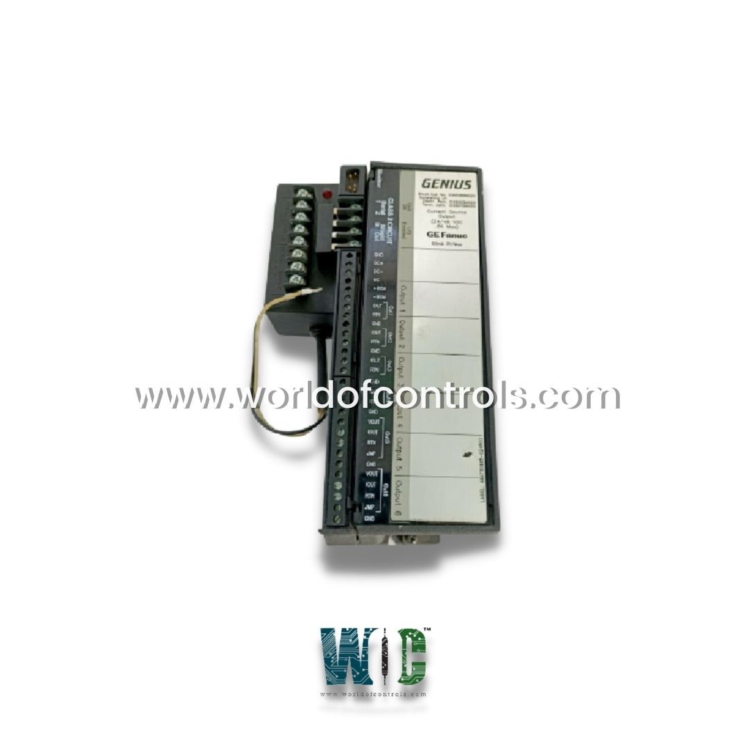
IC660BBA025 is a Genius I/O Module developed by GE. It is a part of Mark I and II control system. The GE Intelligent Platforms/GE Fanuc GE-IP Genius I/O is a 24/48 VDC analog current source block designed to offer reliable analog output capabilities. This block features six analog output circuits, each capable of producing a 4 to 20 mA current loop. It requires no calibration for its operation, simplifying its integration into various systems.
Features
- It provides six independent analog output circuits, each capable of generating a 4 to 20 mA current loop. This feature is ideal for controlling devices such as actuators, valves, and other process equipment that require a consistent and reliable analog current signal.
- These outputs are versatile and can be used for voltage applications, in addition to their standard current loop configuration. This allows for greater flexibility in different industrial applications where both current and voltage signals are needed.
- Equipped with an internal power supply that powers all of its circuits. This design eliminates the need for an external power source when operating 4-20 mA signals, simplifying the setup and reducing the complexity of the system.
- Each of the six output circuits can independently control a 4 to 20 mA current loop. This individual control ensures that each connected device or system receives the appropriate current signal required for optimal operation.
- It includes real-time fault diagnostic capabilities, which provide immediate feedback on any issues or anomalies within the system. Fault messages can be cleared through either a handheld monitor or directly via the CPU, making troubleshooting more efficient and minimizing downtime.
- A dedicated digital output is included in the module for driving a Bus Switching Module. This allows for additional control and integration capabilities, providing more flexibility in how the device is used in larger systems.
Installation and Safety
- Protective Enclosure: It must be installed in a protective enclosure to shield it from airborne contaminants, dust, and other environmental factors that could affect its operation.
- Clean Environment: Ensure that the installation environment is clean and free of contaminants, as dirt or moisture could impair the performance of the module and its components.
- Cooling and Airflow: Proper cooling and airflow are crucial to prevent overheating of the module. The installation area should have sufficient space for ventilation to maintain the appropriate operating temperature for the device.
Configuration Process
- To configure use the IC66 HHM501G handheld monitor (version 4.0 or later). This monitor allows for straightforward programming and setup of the device, streamlining the process of integrating it into your system.
- Enter the device number (or serial bus address) into the handheld monitor. This ensures that the module is correctly recognized and communicated with the rest of the system.
- If required, input the reference number into the monitor to establish proper addressing and communication paths for the device.
- Adjust the scaling settings to match the desired output signal values. This ensures that the output corresponds to the appropriate levels for your specific application, such as controlling flow rates, pressure, or temperature.
- If configuring the device offline (without connecting it to the full system), properly ground the block and install a 75-ohm resistor across the Serial 1 and 2 terminals. This ensures proper operation during offline configuration and prevents damage to the module.
Maintenance and Troubleshooting
- Fault Management: Features advanced diagnostics to monitor the health of the module and detect faults in real-time. If any issues arise, the fault messages can be cleared via the handheld monitor or the CPU, ensuring efficient troubleshooting without lengthy downtime.
- Power Disconnection: Before handling or servicing, always disconnect the power to avoid electrical shock hazards. Proper safety precautions should be followed during installation and maintenance to protect both personnel and equipment.
- Resistor Installation: When configuring the module offline, it is essential to install a 75-ohm resistor across the Serial 1 and 2 terminals. This ensures correct signal transmission and prevents issues during setup.
The WOC team is always available to help you with your Mark I and II requirements. For more information, please contact WOC.
Frequently Asked Questions
What is IC660BBA025?
It is a Genius I/O Module developed by GE under the Mark I and II series.
What are the diagnostic capabilities?
It includes advanced diagnostics that provide real-time fault messages. These messages can be cleared from the handheld monitor or through the CPU, aiding in efficient troubleshooting and maintenance.
Can outputs 5 and 6 be used for applications other than current loops?
Yes, outputs 5 and 6 can be configured for voltage applications if needed, offering additional flexibility for different control scenarios.
How should I handle the block to avoid electrical hazards?
Always ensure that the power is disconnected before handling the block to avoid electrical shock hazards. Follow proper safety procedures during installation and maintenance.
