World Of Controls understands the criticality of your requirement and works towards reducing the lead time as much as possible.
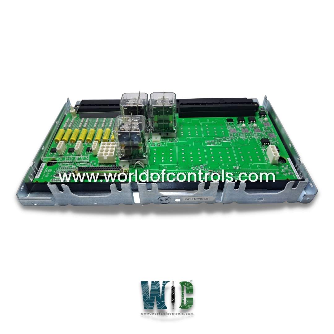
IS210TRPGH2B - Gas Turbine Primary Trip Terminal Board is available in stock which ships the same day.
IS210TRPGH2B - Gas Turbine Primary Trip Terminal Board comes in UNUSED as well as REBUILT condition.
To avail our best deals for IS210TRPGH2B - Gas Turbine Primary Trip Terminal Board, contact us and we will get back to you within 24 hours.
SPECIFICATIONS:
Part Number: IS210TRPGH2B
Manufacturer: General Electric
Series: Mark VI
Product Type: Primary Trip Terminal Board
Trip Solenoids: 3
Solenoid Rated Voltage/Current: 125 V dc
Solenoid Response Time: L/R time
Current Suppression: Metal oxide varistor
Control Relay Coil Voltage Supply: 28 V
Flame Detector Supply Voltage/Current: 335 V dc
Flame Detectors: 8
Availability: In Stock
Country of Origin: United States
Manual: GEH-6721G
FUNCTIONAL DESCRIPTION:
IS210TRPGH2B is a Gas Turbine Primary Trip Terminal Board manufactured and designed by General Electric as part of the Mark VI Series used in GE Speedtronic Control Systems. The TRPG terminal board, controlled by the I/O controller, includes nine magnetic relays organized into three voting circuits to interface with three Electrical Trip Devices (ETDs), which are trip solenoids. It works alongside the TREG to provide both primary and emergency interfaces to the ETDs. Additionally, the TRPG accommodates inputs from eight Geiger Mueller flame detectors used in gas turbine applications. The H1A version, designed for TMR applications, features three voting relays for each trip solenoid. The VTUR board collaborates with the TRPG terminal board. Molded plug cables connect the TRPG to the VME rack where the VTUR board is situated, supporting both simplex and TMR systems.
INSTALLATION:
OPERATION:
The I/O board is responsible for the primary trip function by controlling the relays on the TRPG, which activate the main protection solenoids. In TMR applications, the inputs are voted using a two-out-of-three relay ladder logic voting circuit. The I/O board monitors the current in its relay driver control line to assess the status of the relay coil, determining whether it is energized or de-energized. Additionally, supply voltages are monitored for diagnostic purposes. Diagnostics also track the normally closed contact from each relay on the TRPG board to verify proper operation.
DIAGNOSTICS:
The I/O board manages TRPG diagnostics, which include monitoring feedback from the trip solenoid relay driver and contact, the solenoid power bus, and the flame detector excitation voltage. If any signal exceeds specified limits, a diagnostic alarm is triggered. The connectors JR1, JS1, and JT1 on the terminal board each have a unique ID device that the I/O board interrogates. If a mismatch is detected, a hardware incompatibility fault is generated. The ID device is a read-only chip that contains the terminal board's serial number, board type, revision number, and plug location.
WOC has the largest stock of GE Speedtronic Control System Replacement Parts. We can also repair your faulty boards. We can also supply unused and rebuilt backed-up with a warranty. Our team of experts is available round the clock to support your OEM needs. Our team of experts at WOC is happy to assist you with any of your automation requirements. For pricing and availability on any parts and repairs, kindly get in touch with our team by phone or email.
What is the Gas Turbine Primary Trip Terminal Board?
The GTPTTB is an essential component in a gas turbine control system. It serves as a terminal board where primary trip signals from various protective devices are received and processed to initiate turbine shutdown when necessary.
What is the purpose of the Gas Turbine Primary Trip Terminal Board?
The primary purpose of the GTPTTB is to receive and consolidate critical trip signals from protective devices like temperature sensors, pressure switches, or vibration monitors. These signals are used to ensure the safe shutdown of the gas turbine in case of abnormal operating conditions.
What happens during a turbine trip initiated by the GTPTTB?
When the GTPTTB receives a critical trip signal, it communicates this to the turbine control system, which then initiates a shutdown sequence. This sequence typically involves closing fuel supply valves, activating turbine brakes, and shutting down auxiliary systems to ensure safe turbine shutdown.