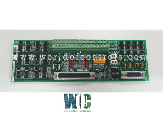
SPECIFICATIONS
Part No.: IS210DSVOH1AA
Manufacturer: General Electric
Country of Manufacture: United States of America (USA)
Board Size: 23.8 cm high x 8.6 cm wide
Mounting: DINRail
Product Type: Servo Terminal Board
Availability: In Stock
Series: Mark VI
Functional Description
IS210DSVOH1AA is a Servo Terminal Board developed by GE. It is part of Mark VI series. It is a compact servo terminal board specifically designed for DIN-rail mounting, allowing for efficient installation in tight spaces. Its modular design supports vertical stacking, which helps optimize cabinet space in control system enclosures.
Features
- The board is equipped with two servo outputs, allowing it to interface with servo actuators for precise control over mechanical movement. Servo coil currents can be jumper-selected within a range of 10 to 120 mA, enabling flexible configuration based on system requirements.
- The terminal board includes six I/O channels dedicated to Linear Variable Differential Transformer (LVDT) sensors, which are commonly used for position feedback in servo control systems. This ensures accurate real-time position monitoring and enhances system stability.
- The board features two active pulse rate inputs, which allow it to be used for flow measurement applications. This is particularly useful in turbine control systems where monitoring fuel flow rates is critical for optimizing performance and efficiency.
- The board incorporates onboard functions and high-frequency decoupling similar to the larger TSVO board, reducing electrical noise and enhancing signal integrity. It includes ID chips that interface with the VSVO processor board, enabling the system to recognize and diagnose the board automatically for enhanced troubleshooting and maintenance.
- The DSVO connects to the VSVO processor board using a 37-pin cable, identical to the ones used by the TSVO board. The terminal blocks are of the high-density Euro-Block type and are permanently mounted to the board. The board is equipped with two connectors (JR1 and J5) that facilitate seamless integration within the Mark VI control system.
- The board is only available in a simplex version, meaning it does not support redundant configurations. If required, two DSVO boards can be connected to a single VSVO processor board for expanded functionality.
Installation Procedure
- Mounting Procedure: The board slides into a plastic holder, which is then mounted onto a DIN-rail inside the control cabinet. This DIN-rail mounting system provides a secure and stable installation while allowing for quick setup and replacement if needed. Additionally, multiple DSVO boards can be stacked vertically, helping to optimize cabinet space and reduce overall wiring complexity.
- Servo I/O Wiring: The servo inputs and outputs (I/O) are connected directly to the Euro-Block type terminal block, which is permanently attached to the board. This ensures secure and durable electrical connections for reliable system operation.
- Recommended Wiring Specifications: To ensure stable signal transmission and minimal interference, the following wiring standards are recommended.
- Wire Type: 18 AWG shielded twisted pair wiring
- Shielding: Prevents electromagnetic interference (EMI), ensuring clean and accurate signal transmission
- Twisted Pair Design: Helps maintain signal integrity by reducing external electrical noise
- Grounding Requirements: The board features six screws designated for SCOM (Signal Common or Ground) connections. To ensure proper grounding Keep ground connections as short as possible to reduce resistance and enhance electrical stability. Proper grounding prevents electrical noise, signal interference, and ground loops, ensuring optimal servo control performance.
Diagnostics
- Servo Output Current Monitoring: The board monitors the servo output current to ensure it remains within acceptable operating limits. If the current exceeds or fails to meet the specified range, a fault condition is triggered. This diagnostic check helps prevent damage to the servo system and ensures proper actuator response.
- LVDT Signal Feedback Monitoring: The board supports up to six Linear Variable Differential Transformer (LVDT) position sensors for precise servo position feedback. The VSVO processor continuously checks these signals, and if an LVDT feedback signal falls out of the allowable range, a fault is triggered. If the affected regulator has two LVDT sensors, the system will automatically remove the faulty sensor from the feedback loop and rely on the functional sensor to maintain control.
This redundancy mechanism ensures uninterrupted operation even if one sensor malfunctions, improving system reliability.
- Composite Diagnostic Alarm (L#DIAG_VSVO): If any of the monitored signals (servo output current or LVDT feedback) become unhealthy, a composite diagnostic alarm (L#DIAG_VSVO) is generated. Detailed diagnostic information can be accessed using the GE Control System Toolbox. Diagnostic signals can be latched, meaning they will remain active even if the issue is momentary. The RESET_DIA signal can be used to clear latched faults once the issue is resolved, allowing for real-time system recovery.
- Connector JR1 ID Verification: The board features a built-in ID device located on connector JR1. This read-only identification chip stores critical board information, including Serial number, Board type, and Revision number.
- Connector location: The VSVO processor automatically reads this ID chip to verify compatibility. If a mismatch is detected between the expected and actual board configuration, a hardware incompatibility fault is triggered. This prevents the use of incorrect or incompatible hardware within the system.
The WOC team is always available to help you with your Mark VI requirements. For more information, please contact WOC.
Frequently Asked Questions
What is IS210DSVOH1AA?
It is a Servo Terminal Board developed by GE under the Mark VI series.
How is the board installed?
The board is mounted on a DIN-rail using a plastic holder. Wiring connections are made through the Euro-Block type terminal blocks. It is recommended to use 18 AWG shielded twisted pair wiring for secure and interference-free connections. Proper grounding is crucial, with six screws dedicated to SCOM (ground) connections.
How does the board communicate with the VSVO processor?
The board connects to the VSVO processor board using a 37-pin cable. The VSVO performs real-time diagnostics and processing for the servo outputs and LVDT feedback signals. Up to two boards can be connected to a single VSVO unit if additional servo channels are required.
