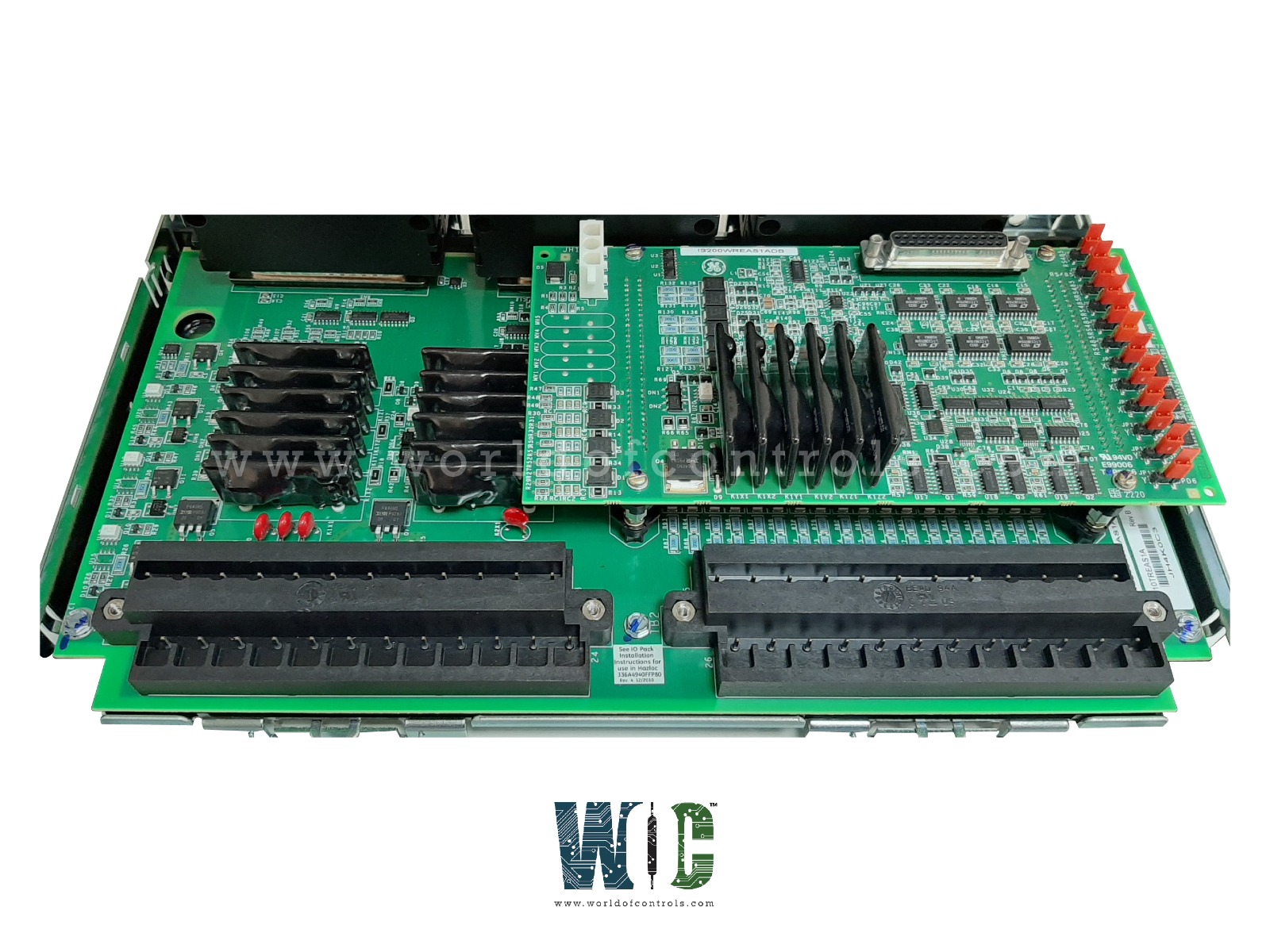
World Of Controls understands the criticality of your requirement and works towards reducing the lead time as much as possible.
IS210TREGH4B - Turbine Emergency Trip Terminal Board is available in stock which ships the same day.
IS210TREGH4B - Turbine Emergency Trip Terminal Board comes in UNUSED as well as REBUILT condition.
To avail our best deals for IS210TREGH4B - Turbine Emergency Trip Terminal Board, contact us and we will get back to you within 24 hours.
SPECIFICATIONS:
Part Number: IS210TREGH4B
Manufacturer: General Electric
Series: Mark VI
Product Type: Turbine Emergency Trip Terminal Board
Number of Channels: 24
Number of inputs: 12
Number of trip solenoids: 3
Number of outputs: 125 V dc
Technology: Surface Mount
Suppression: MOV across the solenoid
Trip interlock isolation: Optical isolation to 1500 V
Dimensions: 17.8 cm wide x 33.02 cm
Operating Temperature: 30 to 65°C
Repair: 3-7 Day
Availability: In Stock
Country of Origin: United States
Manual: GEH-6421I
FUNCTIONAL DESCRIPTION:
IS210TREGH4B is a Turbine Emergency Trip Terminal Board manufactured and designed by General Electric as part of the Mark VI Series used in GE Speedtronic Turbine Control Systems. TREG provides power to three emergency trip solenoids and is controlled by the I/O controller. Up to three trip solenoids can be connected between the TREG and TRPG terminal boards. TREG provides the solenoids' positive side of the DC power, and TRPG provides the negative side. The I/O controller provides emergency overspeed protection, and emergency stop functions, and controls the 12 relays on TREG, nine of which form three groups of three to vote inputs controlling the three trip solenoids. H1B is the primary version for 125v DC applications. Control power from the JX1, JY1, and JZ1 connectors are diode combined to create redundant power on the board for status feedback circuits and powering the economizing relays. Power separation is maintained for the trip relay circuits. In Mark VI systems, the PPRO works with the TREG terminal board. Cables with molded plugs connect TREG to the PPRO module.
OPERATION:
TREG is entirely controlled by the I/O controller, and the only connections to the control modules are the J2 power cable and through the trip solenoids. In simplex systems a third cable carries a trip signal from J1 to the TSVO terminal board, providing a servo valve clamp function upon turbine trip.
DIAGNOSTICS:
The I/O controller runs diagnostics on the TREG board and connected devices. The diagnostics cover the trip relay driver and contact feedback, solenoid voltage, economizer relay driver and contact feedback, K25A relay driver and coil, servo clamp relay driver and contact feedback, and the solenoid voltage source. If any of these do not agree with the desired value then a fault is created. TREG connectors JX1, JY1, and JZ1 have their ID device that is interrogated by the I/O controller. The ID device is a read-only chip coded with the terminal board serial number, board type, revision number, and plug location. When the chip is read by the I/O board and a mismatch is encountered, a hardware incompatibility fault is created.
WOC has the largest stock of OEM Replacement Parts for GE Speedtronic Control Systems. We can also repair your faulty boards and supply unused and rebuilt boards backed up with a warranty. Our team of experts is available round the clock to support your OEM needs. Our team of experts at WOC is happy to assist you with any of your automation requirements. For pricing and availability on parts and repairs, kindly contact our team by phone or email.
How does the Turbine Emergency Trip Terminal Board detect emergency conditions?
The TETTB continuously monitors input signals from sensors that track the turbine's operating parameters, such as vibration, temperature, and pressure. When any of these signals exceed predefined safety thresholds, the Turbine Emergency Trip Terminal Board processes this information and initiates an emergency trip.
What components are included in a Turbine Emergency Trip Terminal Board?
A Turbine Emergency Trip Terminal Board typically includes terminal blocks for wiring connections, relays for switching electrical circuits, indicators and alarms for visual and audible alerts, control circuits for signal processing, and a power supply with battery backup to ensure reliable operation.
How does the Turbine Emergency Trip Terminal Board initiate an emergency trip?
Upon detecting an unsafe condition, the control circuits in the TETTB activate relays that disconnect the turbine from its power source. This effectively shuts down the turbine to prevent damage and ensure safety. Simultaneously, alarms and indicators are activated to notify operators of the emergency.