Specifications
Part No.: IS200VCRCH1A
Manufacturer: General Electric
Country of Manufacture: United States(USA)
Product Type: Discrete Input/Output module
Series: Mark VI
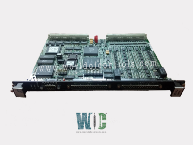
IS200VCRCH1A is a discrete input/output module developed by GE. It is a part of mark VI Speedtronic range of gas and steam turbine management systems. The Contact Input/Relay Output Board (VCRC) and its associated daughterboard accept 48 discrete inputs and control 24 relay outputs from four terminal boards in total. It is a double-width module that fits into a VME I/O rack. This rack has two J3/J4 plugs for connecting cables to the TBCI and TRLY terminal boards. The VCRC is a single slot version of the VCCC that has the same functionality as the VCCC but with contact input cables that plug into the front of the board.
Contact Inputs
- The first 24 dry contact inputs are wired to a contact input terminal board (TBCI), and inputs 25 - 48 require a second terminal board. Dc power is provided for the contacts. Cables with molded plugs connect the terminal board to the VME rack, which contains the processor board.
- For inputs monitoring important turbine variables, high speed scanning and recording at 1 ms rate is available.
- With a time resolution of 1 ms, the sequence of events (SOE) recorder reports all contact openings and closures. Contact chatter and pulse widths as short as 6 ms have been reported.
IS200VCRCH1A Operation
- In the VCRC, input voltages are sampled at the frame rate for control functions and at 1 ms for SOE reporting after passing through optical isolators. The signals are routed to the VCMI via the VME backplane. They are then sent to the controller by the VCMI.
- The dry-contact inputs are powered by a 125 V dc (100 - 145 V dc) floating supply (TBCIH1) or a 24 V dc (18.5 - 32 V dc) floating supply (TBCIH2).
- Filters at each input near the point of signal exit reduce high frequency noise and suppress surge. A 4 ms filter is used to filter out noise and contact bounce. With 125 V dc excitation, the ac voltage rejection (50/60 Hz) is 60 V rms.
- Contact input voltages are fanned out to three VME board racks R, S, and T for TMR applications via plugs JR1, JS1, and JT1. The three VCRCs process the signals, and the results are voted on by the VCMI board in each controller rack. Cables connect VCRC and TRLY and carry relay control signals as well as monitor feedback voltages. The relay board contains relay drivers, fuses, and jumpers.
- TRLY, DRLY, and SRLY are just a few of the relay boards that can be driven. The relay outputs have failsafe features that allow the inputs to vote to de-energize the corresponding relays when a cable is unplugged. Similarly, if communication with the associated VME board fails, the relays are deactivated.
Characteristics
- Size - VCRC 26.04 cm high x 1.99 cm wide x 18.73 cm deep
- Temperature - 0 to 60 ºC
IS200VCRCH1A Diagnostics
Three LEDs at the top of the VCCC front panel indicate status. The normal RUN condition is a flashing green, while the FAIL condition is a solid red. The third LED displays STATUS and is normally off, but displays a steady orange if the board has a diagnostic alarm condition. Among the VAOC diagnostics are the following:
- Diagnostics are used to monitor each output. Voltage drops are sampled and digitized across the local and outer loop current sense resistors, the D/A outputs, and the shutdown relay contacts.
- On the outputs, standard diagnostic information is available, including high and low limit checks, as well as high and low system limit checks (configurable).
- If any of the 48 outputs fails, a composite diagnostic alarm, L3DIAG VCCC, is generated. The toolbox contains information on the individual diagnostics. Individual diagnostic signals can be latched and then reset with the RESET DIA signal if they become healthy.
- Each cable connector on the terminal board has its own ID device, which the I/O processor queries. The ID device is a read-only chip that contains the terminal board serial number, board type, revision number, and the location of the JR, JS, and JT connectors. When the I/O processor reads the ID chip and finds a mismatch, a hardware incompatibility fault is generated.
World of Controls experts are always available to help you with your GE Mark VI needs. Contact us now.
Frequently Asked Questions
What is IS200VCRCH1A?
IS200VCRCH1A is a discrete input/output module developed by GE.
What is the maximum number of inputs and outputs that the module can handle?
The module receives 48 discrete inputs and operates 24 relay outputs using four-terminal boards.
How to obtain this input/output module?
WOC can help with Mark VI components and other turbine control needs. Contact WOC today.
