World Of Controls understands the criticality of your requirement and works towards reducing the lead time as much as possible.
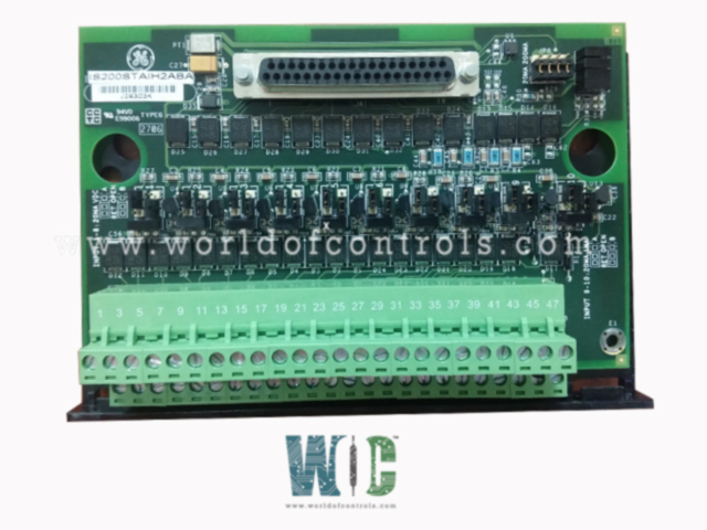
IS200STAIH2ABA - Simplex Analog Input Terminal Board is available in stock which ships the same day.
IS200STAIH2ABA - Simplex Analog Input Terminal Board comes in UNUSED as well as REBUILT condition.
To avail our best deals for IS200STAIH2ABA - Simplex Analog Input Terminal Board, contact us and we will get back to you within 24 hours.
SPECIFICATIONS:
Part Number: IS200STAIH2ABA
Manufacturer: General Electric
Series: Mark VIe
Product Type: Simplex Analog Input Terminal Board
Number of channels: 12
Maximum Lead Resistance: 15 Ω
Outputs: 24 V dc
Size: 15.9 cm high x 10.2 cm wide
Operating Temperature: -30 to +65oC
Technology: Surface mount
Repair: 3-7 Days
Country of Origin: USA
Availability: In Stock
Manual: GEH-6721L
FUNCTIONAL DESCRIPTION:
IS200STAIH2ABA is a Simplex Analog Input Terminal Board manufactured and designed by General Electric as part of the Mark VIe Series used in distributed control systems. The STAI board is a compact analog input terminal board that accepts 10 analog inputs and two analog outputs and connects to the PAIC pack. The 10 analog inputs accommodate two-wire, three-wire, four-wire, or externally powered transmitters. The two analog outputs are 0-20 mA, but one can be jumper configured to 0-200 mA current. Only a simplex version of the board is available. High-density Euro-block type terminal blocks are used. An on-board ID chip identifies the board to the PAIC for system diagnostic purposes. The PAIC I/O pack works with the STAI. The I/O pack plugs into the D-type connector and communicates with the controller over Ethernet. Only simplex systems are supported.
STAI INSTALLATION:
A sheet metal carrier that is mounted on a DIN-rail carries the STAI together with a plastic insulator. The STAI plus insulator can alternatively be mounted to a sheet metal assembly before being fastened directly to a cabinet. Typically, shielded twisted pair (#18 AWG) wires are utilized. There is an I/O cable shield terminal available next to the terminal blocks. It is possible to accept the following analog input and output types:
STAI OPERATION:
The terminal board provides a 24 V DC power supply for all transmitters and transducers. Users can select between current or voltage inputs by adjusting the jumper settings. The system offers two analog output circuits: one is fixed at 4-20 mA, while the other can be configured via jumpers to either 4-20 mA or 0-200 mA, depending on the user's preference. Notably, there is only a single cable connection available, which means the terminal board is unsuitable for TMR (Triple Modular Redundancy) applications, unlike the TBAI model.
STAI DIAGNOSTICS:
The output current is shown by the voltage drop across a series resistor on the board. A diagnostic alarm (fault) is generated by the I/O processor if either of the two outputs becomes unhealthy. The I/O controller queries each ID device that each cable connector on the terminal board has to offer.
The terminal board serial number, board type, revision number, and the placement of the JR, JS, and JT connectors are all encoded on a read-only chip known as the ID device. A hardware incompatibility fault is produced when the I/O controller reads this chip and runs across a mismatch.
STAI CONFIGURATION:
Jumpers are used to configure the terminal board. Refer to the installation diagram to determine where these jumpers should be placed. The available jumpers are as follows:
WOC has the largest stock of GE Distributed Control Systems OEM Replacement Parts. We can also repair your faulty boards and supply unused and rebuilt boards backed up with a warranty. Our team of experts is available around the clock to support your OEM needs. Our team of experts at WOC is happy to assist you with any of your automation requirements. For pricing and availability on any parts and repairs, kindly get in touch with our team by phone or email.
What is the input voltage range for the Simplex Analog Input Terminal Board?
The input voltage range for the Simplex Analog Input Terminal Board is typically designed to work with 24 V DC power supplied to the transmitters and transducers.
How do I configure the analog output for a 0-200 mA range?
To configure the analog output for a 0-200 mA range, adjust the jumper settings on the terminal board to switch the output circuit from the default 4-20 mA to the 0-200 mA configuration.
What is the maximum current that can be drawn from the analog outputs?
The terminal board supports output ranges of 4-20 mA and 0-200 mA. The maximum current for the 0-200 mA output configuration would be 200 mA.