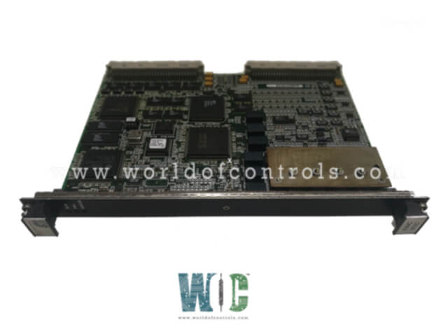
World Of Controls understands the criticality of your requirement and works towards reducing the lead time as much as possible.
IS200VAMAH1A - Simplex Acoustic Monitoring Board is available in stock which ships the same day.
IS200VAMAH1A - Simplex Acoustic Monitoring Board comes in UNUSED as well as REBUILT condition.
To avail our best deals for IS200VAMAH1A - Simplex Acoustic Monitoring Board, contact us and we will get back to you within 24 hours.
SPECIFICATIONS:
Part Number: IS200VAMAH1A
Manufacturer: General Electric
Series: Mark VI
Product Type: Simplex Acoustic Monitoring Board
Number of Channels: 24
Technology: Surface Mount
Number of Transducers: 2
Buffered signal outputs: 2
Common Mode Voltage Range: ±5 V
Dimensions: 11.00 x 9.00 x 3.00
No.of Ribbon Cable Connectors: Two, 20-pin
No.of VMEbus Connectors Two, 96-pin
Repair: 3-7 Day
Availability: In Stock
Country of Origin: United States
Manual: GEH-6421M
FUNCTIONAL DESCRIPTION:
IS200VAMAH1A is a Simplex Acoustic Monitoring Board manufactured and designed by General Electric as part of the Mark VI Series used in GE Speedtronic Turbine Control Systems. The rack-mounted IS200VAMA VME Acoustic Monitoring Board (VAMA) supports the DIN-rail-mounted IS200DDPT Dynamic Pressure Transducer Terminal Board (DDPT). The VAMA/DDPT configuration monitors acoustic or pressure waves in the turbine combustion chamber. The DDPT terminal board supports the simplex mode only and uses the J3 rack connector as the interface to the VAMA. The VAMA/DDPT meets the environment rating for hazardous gases of Class I, Division 2, and provides suppression at all points of signal entry or exit. Each cable has a unique ID chip. The VAMA/DDPT provides two-point calibration, based on reading a reference offset and gain signal. Gas turbine combustion chambers can experience pressure oscillations that cause noise in the audible hearing range. The H1A version of the VAMA/DDPT offers signal conditioning and software that allows the turbine control to monitor the pressure/acoustic waves by reading the conditioned signals from a dynamic pressure transducer. The VAMA/DDPT provides two channels to read the pressure/acoustic wave signals from third-party equipment Vibro-meter or Bently-Nevada. The VAMA provides two dedicated signal conditioning paths to remove the dc component of the signal, modify the gain, and provide an eighth-order or better low-pass filter for anti-aliasing.
INSTALLATION:
To install the VAMA board, first power down the VME processor rack. Slide in the VAMA board and push the top and bottom levers in with your hands to seat its edge connectors. Then tighten the captive screws at the top and bottom of the front panel. These screws serve to hold the board firmly in place and enhance the board's front-ground integrity. The screws should not be used to actually seat the board. Cable connections to the DDPT terminal board are made at the J3 connector on the lower portion of the VME rack, and the J5 connector on the front of the VAMA. These are latching-type connectors to secure the cables. Power up the VME rack and check the diagnostic lights at the top of the front panel, for details refer to the section on diagnostics in this document.
OPERATION:
The VAMA provides signal conditioning for two pressure/acoustic wave inputs and an option to supply either positive 24 V dc or negative 24 V dc to power the pressure sensing equipment. The third-party vendor equipment supported are the Vibro-meter Galvanic Separation Unit Types GSI 1_ _, the Bently-Nevada 86517 with modifications 142533 or 159840 charge amplifier, or the Bently-NevadaTM dynamic pressure charge amplifier 350500.
The Vibro-Meter setup conditions a pico-coulomb output from a dynamic pressure transducer (Vibro-meter CP216 or CP231) through a charge amplifier (Vibro-meter IPC 704) with a current Production representing approximately 125 micro-amps/psi.
The GSI unit provides an output that comprises of an AC signal (approx. ± 2 V peak) that represents the dynamic pressure (gain expressed in milli-volts/psi ) riding on top of a dc bias voltage of approximately +7 V dc. The Vibro-meter GSI unit requires a +24 V dc power supply. Normally, the power supply return for the GSI will be grounded externally and the PCOM on the terminal board is not used. Only use PCOM when the external return ground is not used.
WOC has the largest stock of OEM replacement parts for GE Speedtronic Control Systems. We can also repair your faulty boards and supply unused and rebuilt boards backed up with a warranty. Our team of experts is available round the clock to support your OEM needs. Our team of experts at WOC is happy to assist you with any of your automation requirements. For pricing and availability on parts and repairs, kindly contact our team by phone or email.
What type of output does the dynamic pressure transducer produce?
The dynamic pressure transducer (Vibro-Meter CP216 or CP231) produces a pico-coulomb output, which is further conditioned for monitoring purposes.
What is the purpose of the charge amplifier (Vibro-Meter IPC 704)?
The charge amplifier serves to condition the pico-coulomb output from the dynamic pressure transducer, converting it into a current output representing approximately 125 micro A per psi (pounds per square inch).
What type of signal does the Vibro-Meter GSI unit output, and how is it represented?
The Vibro-Meter GSI unit outputs an AC signal representing the dynamic pressure, with an approximate peak voltage of 2 V. This signal rides on top of a DC bias voltage of approximately 7 V.