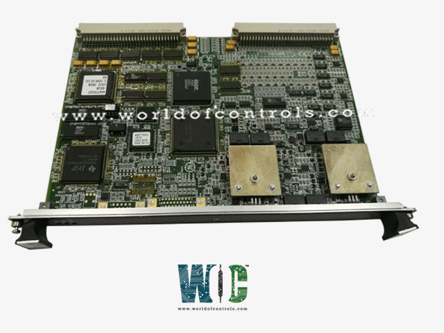
World Of Controls understands the criticality of your requirement and works towards reducing the lead time as much as possible.
IS200VAICH1D - VME ANALOG INPUT CARD is available in stock which ships the same day.
IS200VAICH1D - VME ANALOG INPUT CARD comes in UNUSED as well as REBUILT condition.
To avail our best deals for IS200VAICH1D - VME ANALOG INPUT CARD, contact us and we will get back to you within 24 hours.
Part No.: IS200VAICH1D
Manufacturer: General Electric
Country of Manufacture: United States
Product Type: Contact Input Group Isolation terminal board
Series: Mark VI
IS200VAICH1D is a Contact Input Group Isolation terminal board developed by GE. The VAIC (Analog Input/Output Control) board accepts 20 analog inputs and controls four analog outputs. Ten inputs and two outputs are available on each terminal board. The terminal board is connected to the VME rack, which houses the VAIC processing board, through cables. VAIC converts the inputs to digital values and sends them to the VCMI board, which then sends them to the controller through the VME backplane. The VAIC translates digital values to analog currents and drives them into the customer circuit via the terminal board. Both simplex and triple modular redundant (TMR) applications are supported by VAIC.
The VAIC board comes in two generations, each with its own terminal board. All versions before to and including VAICH1C are included in the original VAIC. This generation also includes VAICH1B. These boards can sustain up to 500 load resistance at the end of 1000 feet of #18 wire while driving 20 mA outputs. For optimal operation, this generation of board requires terminal board TBAIH1B or earlier. They are also compatible with all DTAI terminal board revisions.
To install the V-type board, follow these instructions.
Signal conditioning, an analog MUX, an A/D converter, and a D/A converter are all included on the VAIC board, which receives 20 analog inputs and controls four analog outputs. Jumpers on the terminal board specify the kind of analog input, which can be voltage, 4-20 mA, or 1 mA.
Two of the four analog output circuits are 4-20 mA, while the other two are 4-20 mA or 0-200 mA.
Gas turbine compressor stall detection is performed at 200 Hz by the firmware. There are two stall algorithms available. The first four analog inputs, scanned at 200 Hz, are used by both. Referring to the picture, Tiny (LM) Gas Turbine Compressor Stall Detection Approach, one algorithm is for small LM gas turbines and employs two pressure transducers. The other technique (see the picture, Heavy Duty Gas Turbine Compressor Stall Detection Algorithm) is for heavy-duty gas turbines and makes use of three pressure transducers. For clarity, real-time inputs and configurable parameters are divided. The parameter CompStalType selects the type of algorithm required, either two transducers or three. PS3 is the compressor discharge pressure. A drop in this pressure (PS3 drop) indicates a possible compressor stall. The algorithm also calculates the rate of change of discharge pressure, dPS3dt, and compares these values with configured stall parameters (KPS3 constants).
24 channels per VAIC board (20 AI, 4 AO) (two-terminal boards)
4-20 mA, ±1 mA, ±5 V dc, ±10 V dc
16-bit A/D converter with 14-bit resolution
Less than 31 MW
Within 30 milliseconds, detection and relay operation are completed.
WOC experts are always available to help you with your Mark VI requirements. For more information, please contact WOC.
What does IS200VAICH1D stand for?
The IS200VAICH1D is a VME Analog Input board from General Electric that is part of the Speedtronic Mark VI turbine series.
How can we get information and status on the run and fail issues?
Three LED indicators are located on the front faceplate. These will provide status updates as well as information on difficulties that may cause the system to run or fail.
Where can I get the IS200VAICH1D part?
For IS200VAICH1D terminal board or other turbine control needs, contact WOC.