World Of Controls understands the criticality of your requirement and works towards reducing the lead time as much as possible.
IS200VAICH1C - VME ANALOG INPUT CARD is available in stock which ships the same day.
IS200VAICH1C - VME ANALOG INPUT CARD comes in UNUSED as well as REBUILT condition.
To avail our best deals for IS200VAICH1C - VME ANALOG INPUT CARD, contact us and we will get back to you within 24 hours.
SPECIFICATIONS
Part Number: IS200VAICH1C
Manufacturer: General Electric
Series: Mark VI
Product Type: Analog I/O Board
Function: VAIC Processor Board
Number of Channels: 24 Channels (20 AI, 4 AO)
Availability: In Stock
Country of Origin: USA
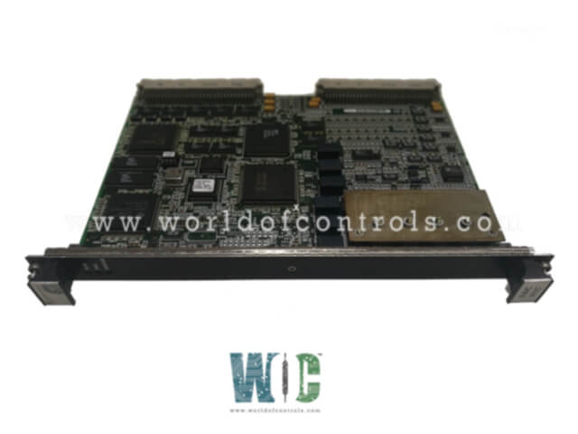
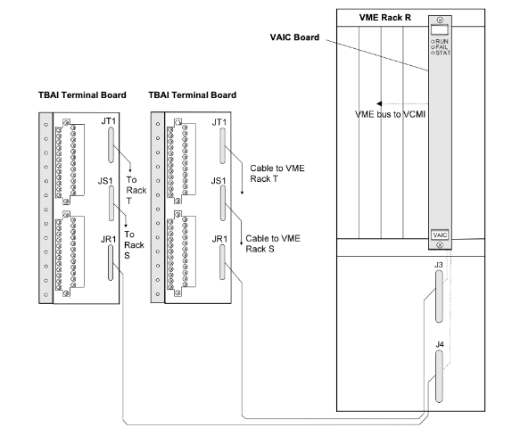
IS200VAICH1C is a VME Analog Input/Output (VAIC) Board manufactured by General Electric as a part of the Mark VI Series used in gas turbine control systems. The Analog Input/Output (VAIC) board accepts 20 analog inputs and controls 4 analog outputs. Each terminal board accepts 10 inputs and 2 outputs. Cables connect the terminal board to the VME rack where the VAIC processor board is located. VAIC converts the inputs to digital values and transfers them over the VME backplane to the VCMI board, and then to the controller. For outputs, the VAIC converts digital values to analog currents and drives these through the terminal board into the customer circuit. VAIC supports both simplex and triple modular redundant (TMR) applications. When used in a TMR configuration, input signals on the terminal board are fanned out to three VME board racks R, S, and T, each containing a VAIC. Output signals are driven with a proprietary circuit that creates the desired current using all three VAICs. In the event of a hardware failure, the bad VAIC is removed from the output and the remaining two boards continue to produce the correct current. When used in a simplex configuration, the terminal board provides input signals to a single VAIC, which provides all of the currents for outputs.
COMPATIBILITY
There are two generations of the VAIC board with corresponding terminal boards. The original VAIC includes all versions prior to and including VAICH1C. VAICH1B is included in this generation. When driving 20 mA outputs these boards support up to 500 load resistance at the end of 1000 ft of #18 wire. This generation of the board requires terminal board TBAIH1B or earlier for proper operation. They also work properly with all revisions of DTAI terminal boards. The newest VAICH1D and any subsequent releases are designed to support higher load resistance for 20 mA outputs drive voltage: up to 18 V is available at the terminal board screw terminals. This permits operation into loads of 800 with 1000 ft of #18 wire with margin. This generation of the board requires TBAIH1C or later, or any revision of STAI.

Fig 1: VAIC, Analog Input Terminal Boards, and Cabling (TMR System)
INSTALLATION
OPERATION
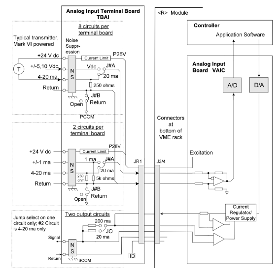
The VAIC board accepts 20 analog inputs, controls 4 analog outputs, and contains signal conditioning, an analog MUX, an A/D converter, and a D/A converter. The type of analog input, either voltage, 4-20 mA, or terminal board. Two of the four analog output circuits are 4-20 mA and the other two can be configured for 4-20 mA or 0-200 mA. Inputs and outputs have noise suppression circuitry to protect against surge and high-frequency noise.

Fig 2: VAIC and Analog Input Terminal Board, Simplex System
In a TMR system, analog inputs fan out to the three control racks from JR1, JS1, and JT1. The 24 V dc power to the transducers comes from all three VME racks and is diode OR selected on the terminal board. Each analog current output is fed by currents from all three VAICs. The actual output current is measured with a series resistor, which feeds a voltage back to each VAIC. The resulting output is the voted middle value (median) of the three currents. The following figure shows VAIC in a TMR arrangement. Transmitters/transducers can be powered by the 24 V dc source in the control system or can be powered independently. Diagnostics monitor each output and a suicide relay disconnects the corresponding output if a fault cannot be cleared by a command from the processor. Hardware filters on the terminal board suppress high-frequency noise. Additional software filters on VAIC provide configurable low pass filtering.
COMPRESSOR STALL DETECTION
VAIC firmware includes gas turbine compressor stall detection, executed at 200 Hz. Two stall algorithms can be selected. Both use the first four analog inputs, scanned at 200 Hz. One algorithm is for small LM gas turbines and uses two pressure transducers (refer to the figure, Small (LM) Gas Turbine Compressor Stall Detection Algorithm). The other algorithm is for heavy-duty gas turbines and uses three pressure transducers (refer to the figure, Heavy Duty Gas Turbine Compressor Stall Detection Algorithm). Real-time inputs are separated from the configured parameters for clarity. The parameter CompStalType selects the type of algorithm required, either two transducers or three. PS3 is the compressor discharge pressure. A drop in this pressure (PS3 drop) indicates a possible compressor stall. The algorithm also calculates the rate of change of discharge pressure, dPS3dt, and compares these values with configured stall parameters (KPS3 constants). The compressor stall trip is initiated by VAIC, which sends the signal to the controller where it is used to initiate a shutdown. The shutdown signal can be used to set all the fuel shut-off valves (FSOV) through any relay output.
Three LEDs at the top of the VAIC front panel provide status information. The normal RUN condition is flashing green, and FAIL is a solid red. The third LED displays STATUS and is normally off, but displays a steady orange if a diagnostic alarm condition exists on the board. Diagnostic checks include the following:
WOC has the largest stock of GE Mark VI replacement spare parts. We can repair your faulty boards. WORLD OF CONTROLS can also supply unused and rebuilt backed up with a warranty. Our team of experts is available round the clock to support your OEM needs. Our team of experts at WOC is happy to assist you with any of your automation requirements. For pricing and availability on any parts and repairs, kindly get in touch with our team by phone or email.
FREQUENTLY ASKED QUESTIONS
How Much Load Resistance Does VME Analog I/O Board Support?
It supports up to 500 watts load resistance at the end of 1000 feet of 18 wire while driving 20 mA outputs.
What are the LEDs on VME Analog I/O Board?
Three LEDs are situated on the top of the board. RUN, FAIL, and STAT is the LEDs on Analog I/O Board that indicate these LEDs.
What is included in VME Firmware?
Gas turbine compressor stall detection is included in the firmware and is performed at 200 Hz on the board.