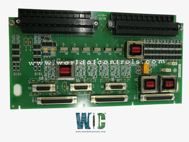
World Of Controls understands the criticality of your requirement and works towards reducing the lead time as much as possible.
IS200TSVOH2B - Servo Valve Interface Terminal Board is available in stock which ships the same day.
IS200TSVOH2B - Servo Valve Interface Terminal Board comes in UNUSED as well as REBUILT condition.
To avail our best deals for IS200TSVOH2B - Servo Valve Interface Terminal Board, contact us and we will get back to you within 24 hours.
SPECIFICATIONS:
Part Number: IS200TSVOH2B
Manufacturer: General Electric
Series: Mark VIe
Product Type: Servo Valve Interface Terminal Board
Operating System: QNX
Power Requirements: +5 V dc, 6 A
Number of input channels: 6
Number of outputs: 2
Trip Solenoid Rating: 125 V dc
Power supply voltage: 24 V dc
Voltage Range: 18 - 32 VDC
Mounting: DIN-rail mounting
Technology: Surface mount
Operating temperature: 40 to 70°C
Size: 17.8 cm high x 33.02 cm
Repair: 3-7 Day
Availability: In Stock
Country of Origin: United States
Manual: GEH-6421M
FUNCTIONAL DESCRIPTION:
IS200TSVOH2B is a Servo Valve Interface Terminal Board manufactured and designed by General Electric as part of the Mark VIe Series used in GE Distributed Turbine Control Systems. The operation of the steam/fuel valves is managed by two electro-hydraulic servo valves linked to the Servo Input/Output (TSVO) terminal board. Linear Variable Differential Transformers (LVDTs) are employed to gauge the position of the valves. The J5 socket located on the front of the VSVO and the J3 or J4 connectors on the VME rack facilitate the connection of two wires to the VSVO. The JR1 connector is utilized by the TSVO for transmitting simplex signals, while the JR1, JS1, and JT1 connectors are used for distributing TMR signals. To implement an external trip from the protection module, plugs JD1 or JD2 should be used.
INSTALLATION:
In the Servo Terminal Board Wiring diagram, connect the wires for the sensors and servo valves directly to two I/O terminal blocks on the terminal board. Each block has 24 connections and can accommodate wire gauges up to #12 AWG, with two screws securing each block in position. Adjacent to each terminal block is a shield termination strip that is grounded to the chassis. For external trip connections, use JD1 or JD2. The VSVO boards in racks R, S, and T should have their J5 connectors linked to the front. Additionally, connect the J1 connectors to the VME rack located beneath the VSVO in racks R, S, and T.
OPERATION:
The VSVO provides four channels for bi-directional servo current outputs, along with LVDT position feedback, LVDT excitation, and pulse rate flux inputs. It can accommodate excitation for up to six LVDT valve position inputs, which are processed by the TSVO. Each servo control loop can utilize one, two, three, or four LVDTs, with three inputs suitable for measuring gas turbine flow. These signals are routed through the TSVO to the J5 connection at the front of the VSVO board.
When not energized, each servo output features a specific suicide relay. This relay, managed by firmware, temporarily shorts the VSVO output signal to the signal common, returning to standard operation only after a manual reset. Diagnostics are in place to monitor the output condition of each servo, including voltage, current, and the status of the suicide relay.
CONFIGURATION:
Jumper JP1 is used to configure the coil current for Servo 1 in a simplex system, while jumper JP4 is designated for Servo 2. For additional information, refer to the Servo Coil Ratings table. In a TMR system, each servo output can have up to three coils. The coil current for Servo 1 is adjusted using Jumpers JP1 to JP3, whereas Jumpers JP4 to JP6 are responsible for setting the coil current for Servo 2. All other configuration tasks are carried out using the toolbox.
WOC has the largest stock of OEM replacement parts for GE Distributed Control Systems. We can also repair your faulty boards and supply unused and rebuilt boards backed up with a warranty. Our team of experts is available round the clock to support your OEM needs. Our team of experts at WOC is happy to assist you with any of your automation requirements. For pricing and availability on parts and repairs, kindly contact our team by phone or email.
How do I wire the terminal board to the servo valve?
Wiring instructions are usually provided in the user manual. Typically, you will connect the power, signal, and feedback lines according to the designated terminal layout.
What troubleshooting steps should I take if the servo valve is not responding?
Start by checking the power supply and connections. Ensure that the wiring is correct, and verify that the control signals are being sent from the controller. Consult the troubleshooting section of the user manual for more detailed steps.
Can the terminal board be used with multiple servo valves?
This depends on the design of the terminal board. Some boards allow for multiple connections, while others are designed for single-valve applications. Refer to the product specifications for guidance.