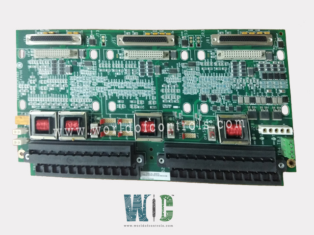
SPECIFICATIONS
Part No.: IS200TSVCH1ABA
Manufacturer: General Electric
Country of Manufacture: United States of America (USA)
Size: 33.02 cm high x 17.8 cm wide
Technology: Surface-mount
Product Type: Servo Input/Output Terminal Board
Availability: In Stock
Series: Mark VIe
Functional Description
IS200TSVCH1ABA is a servo input/output terminal board developed by GE. It is part of Mark VIe series. The Servo Input/Output (TSVC) terminal board serves as an intermediary between two electro-hydraulic servo valves responsible for controlling steam and fuel valves. The positioning of these valves is monitored using linear variable differential transformers (LVDTs), ensuring precision in valve positioning. Specifically designed for compatibility with the PSVO I/O pack and the WSVO servo driver, it's important to note that the TSVC terminal board is not compatible with the VSVO processor.
Terminal Board Features and Compatibility
- Compatibility: Tailored to work seamlessly with the PSVO I/O pack and the WSVO servo driver, ensuring efficient functionality within the designated system setup.
- Control Support: The terminal board supports simplex, dual, and TMR (Triple Modular Redundancy) control configurations, catering to various control requirements within the system architecture.
Power Supply and External Connections
- Power Input: Three 28 V dc supplies are connected through plug J28, providing the necessary power to drive the servo valves and associated components.
- External Trip Inputs: Plugs JD1 or JD2 are designated for an external trip from the protection module, offering additional safety features and trip functionalities.
Functional Capabilities
- Servo Output Channels: The terminal board provides two channels, each featuring bi-directional servo current outputs, LVDT position feedback, LVDT excitation, and pulse rate flow inputs.
- LVDT Valve Position Inputs: It supports up to eight LVDT valve position inputs, allowing flexibility in configuration by offering choices of one, two, three, or four LVDTs for each servo control loop. This capability ensures precise monitoring of valve positions.
- Pulse Rate Inputs: The two pulse rate inputs are specifically allocated for gas turbine fuel flow measurement, enabling accurate monitoring of fuel flow rates.
Relay Control and Diagnostics
- Suicidal Relay Functionality: Each servo output is equipped with an individual suicide relay under firmware control. When de-energized, this relay shorts the PSVO output signal to the signal common. It automatically recovers to nominal limits after receiving a manual reset command.
- Diagnostic Monitoring: The terminal board includes diagnostics that constantly monitor the output status of each servo, including voltage, current, and the status of the suicide relay. These diagnostics ensure the integrity and proper functioning of the servo outputs.
- The board not only facilitates precise control and monitoring of servo valves but also incorporates safety features and comprehensive diagnostics to ensure reliable and efficient operation within the electro-hydraulic control system.
Installation
- I/O Terminal Blocks: Sensors and servo valves are directly wired to two I/O terminal blocks. Each block is firmly secured using two screws and features 24 terminals designed to accommodate wiring of up to 12 AWG gauge.
- Shield Terminal Strip: Adjacent to each terminal block, there's a shield terminal strip connected to the chassis ground. This setup allows for the proper grounding of shielded cables, reducing electromagnetic interference.
- External Trip Wiring: Wiring for external trip functions is connected to either JD1 or JD2, providing an additional layer of safety and trip functionality within the system.
- Triple Modular Redundancy (TMR) Setup: Each servo output can feature three coils in a TMR configuration, enhancing redundancy and reliability in the system's operation.
- Coil Current Selection: The size of the current for each coil is determined using jumpers. JP1, JP3, and JP5 are used to configure the current for Servo 1, while JP2, JP4, and JP6 are used for Servo 2. These jumpers allow for the selection and adjustment of coil currents, ensuring compatibility and optimal performance of the servo outputs.
- Wiring Gauge: Use wiring of up to 12 AWG gauge for the sensors and servo valves to ensure appropriate power and signal transmission.
The WOC team is always available to help you with your Mark VIe requirements. For more information, please contact WOC.
Frequently Asked Questions
What is IS200TSVCH1ABA?
It is a servo input/output terminal board developed by GE under the Mark VIe series.
What actions are taken if the output servo current or LVDT signal is out of limits or unresponsive?
If the output servo current exceeds specified limits or fails to respond, or if the regulator feedback signal (LVDT) is out of acceptable limits, a fault is triggered. In cases where a regulator has two sensors, the faulty sensor is isolated from the feedback calculation, and the system relies on the functioning sensor.
What happens if any of the above signals become unhealthy?
If any of the aforementioned signals-output servo current, LVDT signal become unhealthy, a composite diagnostic alarm labeled DIAG_PSVO is activated. Detailed information regarding individual diagnostics is available through the ToolboxST application, allowing for a comprehensive understanding of the specific faults or issues.
How are the diagnostic signals managed or reset if they become healthy again?
The diagnostic signals can be individually latched when triggered. Upon resolution or when the signals return to a healthy state, they can be reset using the RESET_DIA signal.
What role does the ID device on the cable connectors play?
Each cable connector on the terminal board is equipped with an ID device-a read-only chip containing crucial information such as the terminal board's serial number, type, revision number, and the J connector location. The I/O processor queries this chip, and if a discrepancy or mismatch is detected, indicating a hardware incompatibility, a fault is generated.
