SPECIFICATIONS
Part No.: IS200TRTDH1B
Manufacturer: General Electric
Country of Manufacture: United States(USA)
Product Type: RTD Input Terminal Board
Series: Mark VI
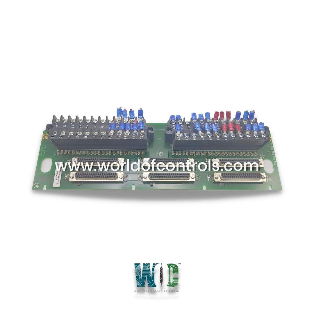
IS200TRTDH1B is an RTD Terminal Card developed by General Electric. The TRTD terminal board supports 16 three-wire RTD inputs. These inputs are connected to two barrier terminal blocks. Surge and high frequency noise are protected by noise suppression circuitry in the inputs. TRTD communicates with one or more I/O processors, which convert input temperature values to digital temperature values and send them to the controller. TRTDH1B is a TMR version that uses six DC-type connectors to fan out signals to three VRTD boards.
IS200TRTDH1B Installation
- Connect the wires for the 16 RTDs to the terminal board's two terminal blocks. Each block is held together with two screws and has 24 terminals that accept wires up to #12 AWG. To the left of each terminal block is a shield terminal strip connected to chassis ground.
- It is necessary to use double-shielded wire. The shield terminal strip must be used to terminate all shields. End shields that are located at the end device. H1B provides redundant RTD inputs in a TMR Mark VI control system by fanning the inputs to three VRTD boards in the R, S, and T racks.
- The inputs meet the same environmental, resolution, suppression, and function requirements, as well as the same codes as the H1C terminal board.
Operation
- TRTD provides a 10 mA dc multiplexed (not continuous) excitation current to each grounded or ungrounded RTD. With a maximum two-way cable resistance of 15, the 16 RTDs can be located up to 300 m (984 ft) from the turbine control cabinet.
- The I/O processor's A/D converter samples each signal and excitation current four times per second in normal mode scanning and 25 times per second in fast mode scanning, with a time sample interval related to the power system frequency.
- The linearization for the 15 RTD types is done by software. Out-of-range values detect RTD open and short circuits. To avoid adverse effects on other input channels, an RTD that is determined to be outside the hardware limits is removed from the scanned inputs.
- Repaired channels are automatically or manually reinstated in 20 seconds. At signal entry, all RTD signals have high-frequency decoupling to ground. The I/O processor's RTD multiplexing is coordinated by redundant pacemakers, so that the loss of a single cable or I/O processor does not result in the loss of any RTD signals in the control database.
Characteristics
- Eight channels per terminal board
- Span 0.3532 to 4.054 V
- Maximum lead resistance 15 ohm maximum two-way cable resistance
- Fault detection - High/low (hardware) limit check, High/low (software) system limit check,
- Failed ID chip
IS200TRTDH1B Diagnostics
- Each RTD type has hardware limit checking based on predefined (non-configurable) high and low levels set near the operating range's extremes. When this limit is reached, a logic signal is generated and the input is no longer scanned. If any of the input's hardware limits is exceeded, a composite diagnostic alarm, L3DIAG xxxx, referring to the entire board is generated. The toolbox contains information on the individual diagnostics. Individual diagnostic signals can be latched and then reset with the RESET DIA signal.
- System limit checking is performed on each RTD input based on configurable high and low levels. These limits can be configured for enable/disable as well as latching/non-latching to generate alarms. RESET SYS clears all out-of-limit signals. Limit logic signals are voted in TMR systems, and the resulting composite diagnostic is present in each controller.
- Each RTD's resistance is checked and compared to the correct value; if it is too high or too low, a fault is generated.
- Each connector has its own ID device, which the I/O processor board interrogates. A read-only chip containing the terminal board serial number, board type, revision number, and connector location is coded with the terminal board ID. When a mismatch occurs, a hardware incompatibility fault is generated.
Features
- JTA/JTB, JSA/JSB, and JRA/JRB are the cable connector labels. When repair is required, the terminal blocks are designed to unplug from the board. Each terminal block has twenty-four screw connections and may receive up to eight three-wire RTD inputs. A shield bar has been placed directly to the left of these components.
- The PCB's six connectors are used to fan signal out to three VRTD boards. It is compatible with both simplex and TMR applications. It is vital to remember that the board does not support quick scanning.
- Each RTD connected has the option of being grounded or ungrounded. Each of these components, which can be located up to 300 meters away from the turbine control cabinet, receives a 10 mA dc multiplexed excitation from the board.
- At 400 degrees Fahrenheit, RTD accuracy ranges from 2 degrees Fahrenheit to 10 degrees Fahrenheit. There are no jumper switches or hardware settings.
- The board has both hardware and software system limit checking. If the read-only chip on the board is not compatible, a hardware incompatibility fault will be generated.
WOC Team is always available to assist you with your Mark VI needs. Please contact WOC for further details.
Frequently Asked Questions
What is IS200TRTDH1B?
IS200TRTDH1B is an RTD Terminal Card developed by General Electric.
What are the connectors on the component for?
The connectors are used to fan signal out to three VRTD boards.
How to Obtain IS200TRTDH1B?
World of Controls provides IS200TRTDH1B as well as other turbine control products. Contact WOC.
