World Of Controls understands the criticality of your requirement and works towards reducing the lead time as much as possible.
IS200TRPGH1ACB - Primary Trip Termination Board is available in stock which ships the same day.
IS200TRPGH1ACB - Primary Trip Termination Board comes in UNUSED as well as REBUILT condition.
To avail our best deals for IS200TRPGH1ACB - Primary Trip Termination Board, contact us and we will get back to you within 24 hours.
SPECIFICATIONS:
Part Number: IS200TRPGH1ACB
Manufacturer: General Electric
Series: Mark VIe
Trip Solenoids: 3
Solenoid Rate Voltage/Current: 125 V dc
Flame Detectors: 8
Number of output relay channels: 12
Product Type: Primary Trip Termination Board
Maximum Load Current: 24 V dc
Technology: Surface Mount
Size: 17.8 cm wide x 33.02 cm high
Temperature: -30 to 65ºC
Repair: 3-7 Days
Weight: 2.00 lbs
Country of Origin: USA
Availability: In Stock
FUNCTIONAL DESCRIPTION:
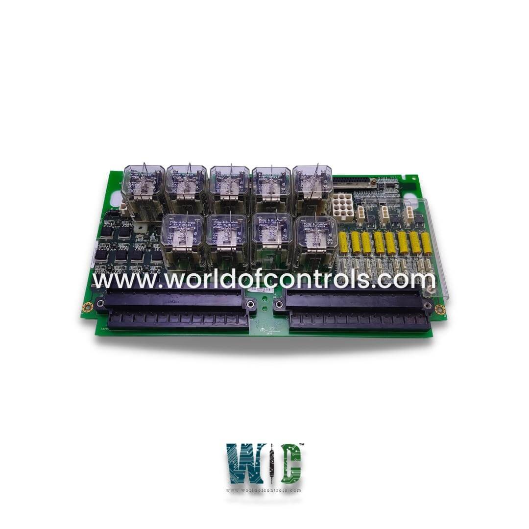
IS200TRPGH1ACB is a Primary Trip Termination Board manufactured and designed by General Electric as part of the Mark VIe Series used in GE Distributed turbine control systems. The TRPG is managed by the primary turbine protection controller (VTUR or PTUR) and includes nine magnetic relays arranged in three voting circuits, which interface with three trip solenoids (ETDs). It works in conjunction with the TREG to form both the primary and emergency connections to the ETDs. In the Mark VIe system, the TRPG is controlled by PTUR packs on the TTURH1C board, supporting both Simplex and TMR configurations. The D-Type connectors on TTURH1C are linked to the TRPG and accommodate I/O packs. Additionally, the TRPG accepts inputs from eight flame detectors, which are essential for gas turbine operations. Two types of boards are utilized within this system.
OPERATIONS:
The I/O pack/board provides the primary trip function by controlling the relays on TRPG, which trip the main protection solenoids. In TMR applications, the three inputs are voted in hardware using a relay ladder logic two-out-of-three voting circuit. The I/O pack/board monitors the current flow in its relay driver control line to determine its energized or de-energized vote/status of the relay coil contact status. Supply voltages are monitored for diagnostic purposes. A normally closed contact from each relay on TRPG is monitored by the diagnostics to determine its proper operation.
FLAME DETECTORS:
The primary protection system monitors signals from eight Geiger-Mueller flame detectors. With no flame present, the detector charges up to the supply voltage. The presence of flame causes the detector to charge to a level and then discharge through TRPG. As the flame intensity increases, the discharge frequency increases. When the detector discharges, the I/O pack/board, and TRPG convert the discharged energy into a voltage pulse. The pulse rate varies from 0 to 1,000 pulses/sec. These voltage pulses are fanned out to all three modules. Voltage pulses above 2.5 volts generate a logic high, and the pulse rate over a 40 ms period is measured in a counter.
WOC holds the largest inventory of GE Distributed control system replacement parts. We also offer repair services for faulty boards and supply both new and refurbished boards, all backed by a warranty. Our expert team is available 24/7 to support your OEM requirements. For inquiries about pricing and availability of parts or repair services, please reach out to our team via phone or email. We’re here to assist with all your automation needs.
What is the primary function of the TRPG system?
The TRPG system controls relays that trip the main protection solenoids, providing the primary trip function in turbine protection. It works with the TREG system to form the interface between the primary and emergency sides of the trip solenoids (ETDs).
How does the TRPG system handle multiple inputs in a TMR setup?
In a Triple Modular Redundant (TMR) setup, the TRPG system uses a relay ladder logic with a two-out-of-three voting circuit. This ensures reliable decision-making by voting on inputs across three modules.
How does the TRPG system process signals from flame detectors?
The flame detectors generate voltage pulses based on flame intensity. The I/O pack/board and TRPG convert the discharge from the detectors into voltage pulses, which are sent to all three modules. The pulse rate ranges from 0 to 1,000 pulses per second, and the system measures the pulse rate over a 40-millisecond time period.
What is the significance of the voltage pulse threshold in the flame detection system?
Voltage pulses above 2.5 volts are considered logic high, and they indicate the presence of a flame. The system uses these pulses to assess the flame intensity and trigger appropriate actions in the turbine protection system.