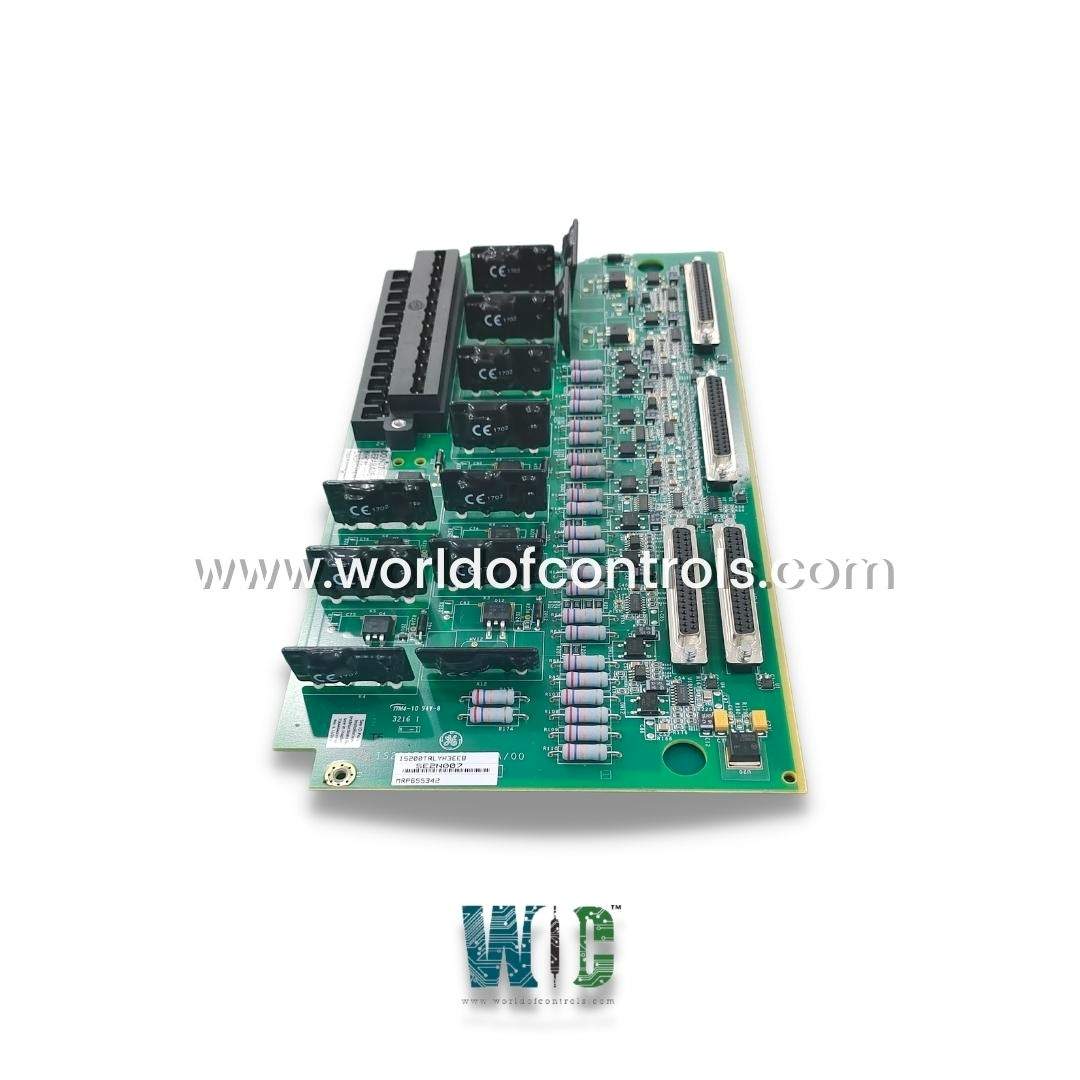
World Of Controls understands the criticality of your requirement and works towards reducing the lead time as much as possible.
IS200TRLYH3E - Solid-State Relay Output Terminal Board is available in stock which ships the same day.
IS200TRLYH3E - Solid-State Relay Output Terminal Board comes in UNUSED as well as REBUILT condition.
To avail our best deals for IS200TRLYH3E - Solid-State Relay Output Terminal Board, contact us and we will get back to you within 24 hours.
SPECIFICATIONS:
Part Number: IS230TRLYH3E
Manufacturer: General Electric
Series: Mark VIe
Product Type: Solid-State Relay Output Terminal Board
Number of channels: 12
Maximum operating voltage: 250 V rms
Maximum off-state leakage: 3mA rms
Power supply voltage: 28 V dc
Voltage Range: 14 to 32 V dc
Max response time ON: 1ms
Mounting: DIN-rail mounting
Technology: Surface mount
Operating temperature: -30 to 65°C
Size: 17.8 cm wide x 33.02 cm
Repair: 3-7 Day
Availability: In Stock
Country of Origin: United States
Manual: GEH-6421M
FUNCTIONAL DESCRIPTION:
IS200TRLYH3E is a Solid-State Relay Output Terminal Board manufactured and designed by General Electric as part of the Mark VIe Series used in GE Distributed Gas Turbine Control Systems. The solid-state Relay Output (TRLYH1E) terminal board is a 12-output relay board using solid-state relays for the outputs and featuring isolated output voltage feedback on all 12 circuits. The solid-state relays allow the board to be certified for Class 1 Division 2 applications. The use of solid-state relays requires three different board types:
Unlike the form-C contacts provided on the mechanical relay boards, all 12 outputs on TRLYH1E are single, NO, contacts. There is no user solenoid power distribution on the board. In the Mark VIe system, the TRLY works with the PDOA I/O pack and supports simplex and TMR applications. PDOA plugs into the DC-37 pin connectors on the terminal board. Connector JA1 is used on simplex systems, and connectors JR1, JS1, and JT1 are used for TMR systems.
INSTALLATION:
Connect the wires for the 12 solenoids directly to the I/O terminal block on the terminal board as shown in the figure, TRLYH1E Terminal Board Wiring. The terminal block is held down with two screws and has 24 terminals accepting up to #12 AWG wires. The dc relays are unidirectional, so care should be taken about polarity when connecting load to these relays. A shield terminal strip attached to the chassis ground is located immediately to the left of each terminal block. The solenoids must be powered externally by the customer.
OPERATION:
NO solid-state relays, relay drivers, and output monitoring are mounted on TRLYH1E. During power-up, relays stay de-energized while connected to any control. The relay outputs have a failsafe feature that votes to de-energize the corresponding relay when a cable is unplugged or communication with the associated I/O processor is lost.
For simplex operation, control signals and relay output voltage feedback signals pass between the I/O processor and TRLY through JA1. For TMR applications, relay control signals are fanned into TRLY from the three I/O processors R, S, and T through plugs JR1, JS1, and JT1. These signals are voted and the result controls the corresponding relay driver. Power for the relay drivers comes in from all three I/O processors and is diode-shared. The following figure shows TRLYH1E in a TMR system.
WOC has the largest stock of GE Distributed Gas Turbine Control System Replacement Parts. We can also repair your faulty boards. WORLD OF CONTROLS can also supply unused and rebuilt backed-up with a warranty. Our team of experts is available round the clock to support your OEM needs. Our team of experts at WOC is happy to assist you with any of your automation requirements. For pricing and availability on any parts and repairs, kindly get in touch with our team by phone or email.
How are control signals and feedback voltages transmitted in simplex operation?
In simplex configurations, D-type connectors, specifically connector JA1, facilitate the transmission of control signals and monitor feedback voltages between the I/O processors and the board.
What are the specifications of the relays on the board?
The relays on the board are driven at the frame rate and have a 3.0 A rating. They are capable of handling a contact-to-contact voltage of 500 V AC and a coil-to-contact voltage of 1,500 V AC for one minute. The typical time to operate a relay is 10 ms.
How are transient voltage spikes suppressed in Relays 1-6?
Relays 1-6 are equipped with 250 V metal oxide varistors (MOV) between the normally open (NO) and power return terminals. These MOVs provide transient suppression, protecting the relay and connected equipment from voltage spikes.