SPECIFICATIONS
Part No.: IS200TRLYH1CDC
Manufacturer: General Electric
Country of Manufacture: United States of America (USA)
Temperature Operating: -30 to 65oC
Size: 17.8 cm wide x 33.02 cm high
Temperature: -30 to 65oC
Number of relay channels: 12
Rated voltage on relays: Nominal 125 V dc or 115/230 V ac
Product Type: Relay Output terminal board
Availability: In Stock
Series: Mark VI
Functional Description
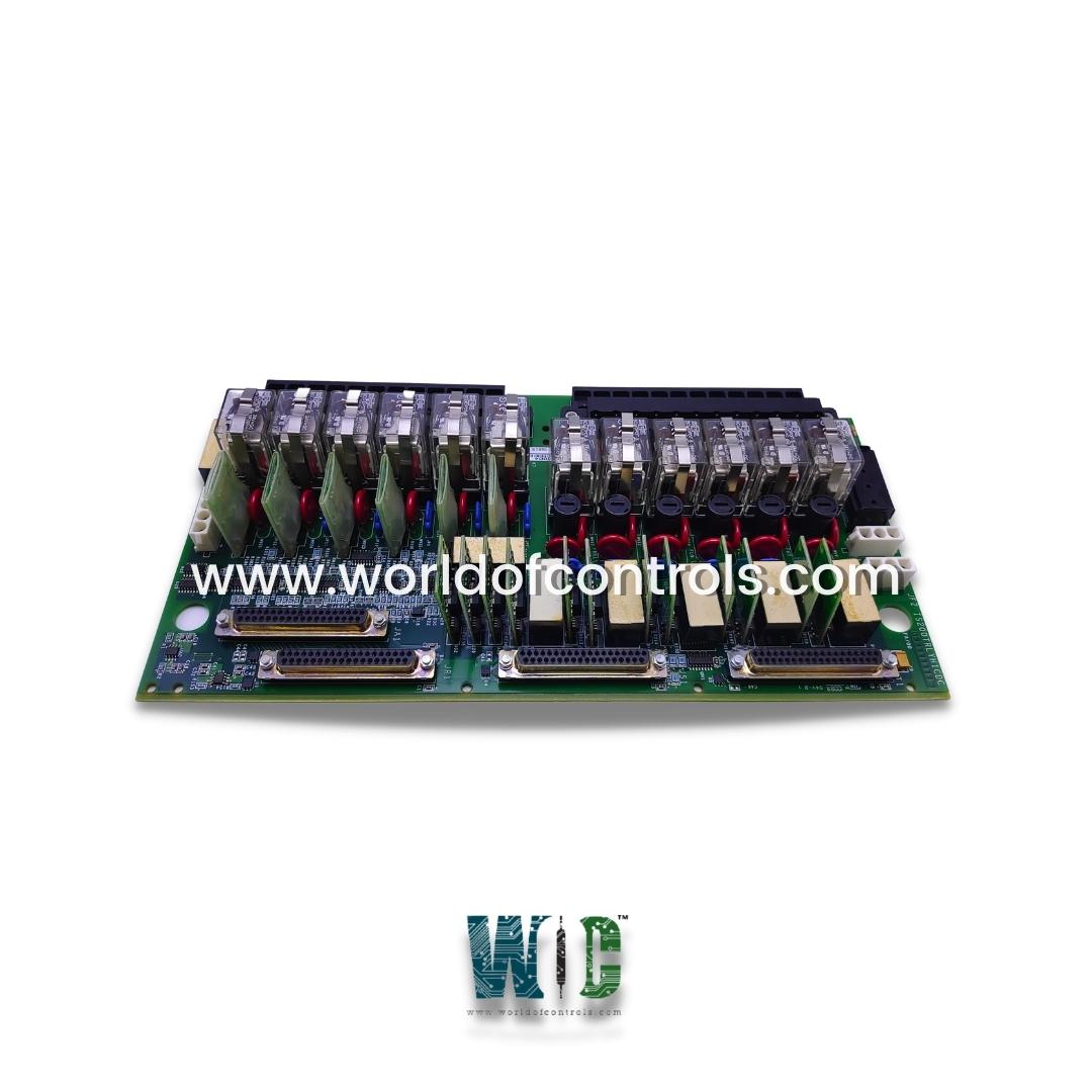
IS200TRLYH1CDC is a Relay Output terminal board developed by GE. It is a part of the Mark VI control system. The terminal board accommodates 12 plug-in magnetic relays, with the initial six relay circuits designed as Form-C contact outputs for controlling external solenoids. It includes provisions for a standard 125 V DC or 115 V AC power source, featuring fuses and on-board suppression for safe operation of field solenoid power. Similarly, the TRLYH2C terminal board also houses 12 plug-in magnetic relays.
Features
- The terminal board integrates relay drivers, which are essential for activating the plug-in magnetic relays installed on the board. These drivers ensure precise and reliable operation of the relays, enabling them to switch external circuits as required.
- Fuses are strategically mounted on the board to protect against overcurrent conditions. They safeguard the circuitry and components from damage due to excessive current flow, ensuring the longevity and reliability of the terminal board.
- Jumpers on the board are used for configuration purposes, allowing for flexibility in how the relays and other components are connected and operated within the system.
- Relays 1-6 on the board are equipped with a 250 V Metal Oxide Varistor (MOV) for transient suppression. This component protects the relays from voltage spikes and transient surges that could occur in the circuit, ensuring stable and reliable operation over time.
- The relays themselves are rated for a 3.0 A AC current, allowing them to handle moderate electrical loads with ease. They operate at the frame rate of the control system, responding swiftly to control signals to switch their respective circuits on or off.
Operational Characteristics
- Time to Operate: The relays on the board typically operate within a fast response time of 10 milliseconds. This quick response ensures efficient control of external devices and systems.
- Fail-Safe Feature: A notable feature of the relay outputs on the TRLYH1C board is their fail-safe mechanism. In the event that a cable becomes unplugged or communication with the associated I/O board is lost, the terminal board initiates a fail-safe action. This action involves voting to de-energize the corresponding relay, thereby preventing unintended operation or potential hazards in the controlled system.
Fault Detection
- Loss of Relay Excitation Current: One of the primary fault detection mechanisms on the board is designed to detect loss of relay excitation current. This feature monitors the current flowing through the relays to ensure they remain energized during operation. If the excitation current drops below a specified threshold or ceases altogether, indicating a fault or malfunction, the board initiates corrective action by de-energizing the affected relays. This prevents unintended operation or potential damage to connected devices.
- NO Contact Voltage Disagreement with Command: Another critical fault detection mechanism involves monitoring the Normally Open (NO) contact voltage for discrepancies with the commanded state. The board compares the actual voltage at the NO contacts with the expected voltage based on the control command. If a disagreement is detected—such as a voltage level that deviates significantly from the commanded state - the board interprets this as a fault condition. In response, it de-energizes the corresponding relays to prevent incorrect operation or unsafe conditions in the controlled system.
- Unplugged Cable or Loss of Communication with I/O Board: The terminal board includes detection capabilities for unplugged cables or loss of communication with the associated I/O board. This feature ensures continuous monitoring of communication links between the terminal board and the control system. If a cable becomes unplugged or communication is interrupted or lost, the board detects this fault condition promptly. In such cases, to maintain operational safety and integrity, the terminal board initiates a fail-safe response by de-energizing the relays connected to the affected communication path. This action prevents unreliable operation or potential hazards that could arise from a lack of communication or connectivity issues.
- Safety and Operational Integrity: By integrating these advanced fault detection mechanisms, the terminal board enhances safety and operational integrity in industrial environments. It ensures that potential faults related to relay operation, voltage discrepancies, or communication failures are promptly identified and addressed. This proactive approach helps maintain reliable performance and prevents operational disruptions, contributing to overall system reliability and safety.
The WOC team is always available to help you with your Mark VI requirements. For more information, please contact WOC.
Frequently Asked Questions
What is IS200TRLYH1CDC?
It is a Relay Output terminal board developed by GE under the Mark VI series.
How does the board detect loss of relay excitation current?
The board monitors the current flowing through the relays to detect any loss of excitation current. If the current falls below a specified threshold or ceases altogether, indicating a fault or malfunction, the board automatically de-energizes the affected relays to prevent unintended operation or damage to connected devices.
What is NO contact voltage disagreement with command detection?
This feature involves comparing the actual voltage at the Normally Open (NO) contacts with the voltage commanded by the control system. If there is a significant discrepancy between the expected and actual voltages, the board interprets this as a fault condition. It responds by de-energizing the corresponding relays to ensure correct operation and prevent unsafe conditions in the controlled system.
