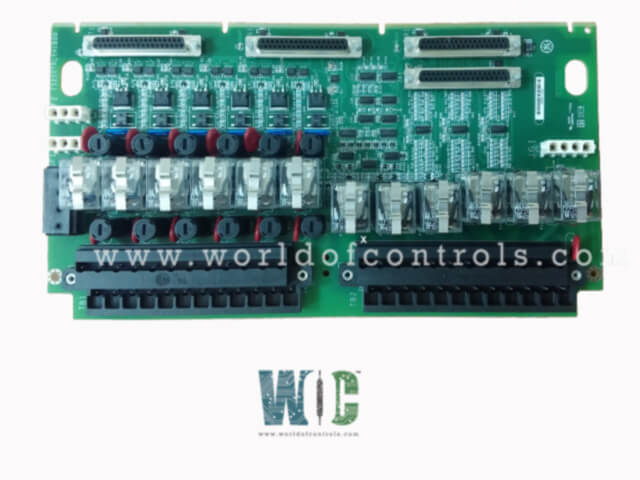
World Of Controls understands the criticality of your requirement and works towards reducing the lead time as much as possible.
IS200TRLYHIB - Relay Output Terminal Board is available in stock which ships the same day.
IS200TRLYHIB - Relay Output Terminal Board comes in UNUSED as well as REBUILT condition.
To avail our best deals for IS200TRLYHIB - Relay Output Terminal Board, contact us and we will get back to you within 24 hours.
SPECIFICATIONS:
Part Number: IS200TRLYHIB
Manufacturer: General Electric
Series: Mark VIe
Product Type: Relay Output Terminal Board
Number of channels: 16
Relay Type: SPDT
Relay Contact Rating: 10A
Input Voltage Range: 12V, 24V
Number of Relay Channels: 4, 8
Relay Switching Current: Max 10A
Mounting Type: DIN rail
Output Resolution: 12-bit
Output Impedance: 10 Ohm
Analog outputs: 0-20 mA
Size: 17.8 cm wide x 33.02 cm
Operating Temperature: -30 to 65ºC
Technology: Surface Mount
Repair: 3-7 Day
Availability: In Stock
Country of Origin: United States
Manual: GEH-6721D
FUNCTIONAL DESCRIPTION:
IS200TRLYHIB is a Relay Output Terminal Board manufactured and designed by General Electric as part of the Mark VIe Series used in the GE Distributed Turbine Control Systems. The Relay Output with TMR contact voting (TRLY) terminal board provides 12 contact-voted relay outputs. The board holds 12 sealed relays in each TMR section, for a total of 36 relays. The relay contacts from R, S, and T are combined to form a voted Form A (NO) contact. 24/125 V dc or 115 V ac can be applied.
TRLY does not have power distribution. For the Mark VI and VIe control systems, an optional power distribution board, IS200WPDFH1A, can be added so that a standard 125 V dc or 115 V ac source, or an optional 24 V dc source with individual fuses, can be provided for field solenoid power. IS200WPDFH2A provides a single fuse in the high side (pin 1 of J1–J4) of each power distribution circuit for ac applications where a fuse in neutral return wire (pin 3 of J1–J4) is not desirable. TRLY2F is the same as TRLY1F except that the voted contacts form a Form B (NC) output. Both boards can be used in Class 1 Division 2 applications.
INSTALLATION:
Connect the wires for the 12 solenoids directly to two I/O terminal blocks on the terminal board as shown in the following figure, TRLY1F Terminal Board Wiring. Each block is held down with two screws and has 24 terminals accepting up to #12 AWG wires. A shield termination strip attached to the chassis ground is located immediately to the left side of each terminal block. Solenoid power for outputs 1-12 is available if the WPDF daughterboard is used. Alternatively, customer power may be wired to the terminal block. The 28 V dc power for the terminal board relay coils and logic comes from the three I/O processors connected at JR1, JS1, and JT1.
OPERATION:
The 28 V dc power for the terminal board relay coils and logic comes from the three I/O processors connected at JR1, JS1, and JT1. The same relays are used for ac voltages and dc voltages, as specified in the Specifications section. TRLY1F and 2F use the same relays with differing circuits. Relay drivers are mounted on the TRLY1F and drive the relays at the frame rate. The relay outputs have a failsafe feature that votes to de-energize the corresponding relay when a cable is unplugged or communication with the associated I/O board or I/O pack is lost.
This board only supports TMR applications. The relay control signals are routed into TRLY1F from the three I/O processors R, S, and T through plugs JR1, JS1, and JT1. These signals directly control the corresponding relay driver for each TMR section R, S, and T. Power for each section’s relay coils comes in from its own I/O processor and is not shared with the other sections. TRLY features TMR contact voting. The relay contacts from R, S, and T are combined to form a voted Form A (NO) contact. 24/125 V dc or 115 V ac can be applied. TRLY is the same except that the voted contacts form a Form B (NC) output. The following figure shows the TMR voting contact circuit.
WOC has the largest stock of OEM Replacement Parts for GE Distributed Turbine Control Systems. We can also repair your faulty boards and supply unused and rebuilt boards backed up with a warranty. Our team of experts is available round the clock to support your OEM needs. Our team of experts at WOC is happy to assist you with any of your automation requirements. For pricing and availability on parts and repairs, kindly contact our team by phone or email.
What is a Relay Output Terminal Board?
A Relay Output Terminal Board is an electrical component used to manage multiple relay outputs and connect them to external devices such as motors, lights, alarms, or other control systems. It simplifies wiring and management by providing a centralized connection point for the relays.
What types of relays can be used with the Relay Output Terminal Board?
Relay Output Terminal Boards typically support SPDT (Single Pole Double Throw), DPDT (Double Pole Double Throw), and other relay types. The specific type depends on the model and application.
What are the common voltage ratings for Relay Output Terminal Boards?
The most common voltage ratings for relay output terminal boards are 12V, 24V, 48V, and 230V (AC/DC), but this can vary depending on the relay model and intended use.
What is the maximum current rating for the relays?
Relay Output Terminal Boards typically handle up to 10A (AC) or 5A (DC) per relay, though this may vary depending on the model and relay type.