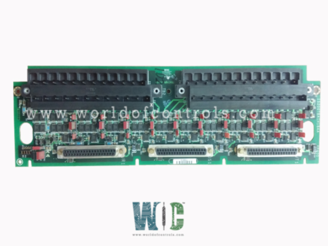
World Of Controls understands the criticality of your requirement and works towards reducing the lead time as much as possible.
IS200TBAIH1B - Analog Input Terminal Board is available in stock which ships the same day.
IS200TBAIH1B - Analog Input Terminal Board comes in UNUSED as well as REBUILT condition.
To avail our best deals for IS200TBAIH1B - Analog Input Terminal Board, contact us and we will get back to you within 24 hours.
SPECIFICATIONS:
Part Number: IS200TBAIH1B
Manufacturer: General Electric
Series: Mark VIe
Board Type: Analog Input Terminal Board
Number of inputs: 12
Number of outputs: 5A
Power supply voltage: 125 V dc
MPU Pulse Rate Range: 2 Hz
Contact voltage sensing: 20 V dc
Operating Temperature Range: -30°C to +65°C
Dimensions: 10.16 cm wide x 33.02 cm high
MPU Input Circuit Sensitivity: 27 mV
Mounting Type: Surface-mount
Repair: 3-7 Day
Availability: In Stock
Country of Origin: United States
Manual: GEH-6721D
FUNCTIONAL DESCRIPTION:
IS200TBAIH1B is an Analog Input Terminal Board manufactured and designed by General Electric as part of the Mark VIe Series used in GE Distributed Turbine Control Systems. The Analog Input terminal board supports 10 analog inputs and two outputs. The 10 analog inputs accommodate two-wire, three-wire, four-wire, or externally powered transmitters. The analog outputs can be set up for 0-20 mA or 0-200 mA current. Inputs and outputs have noise suppression circuitry to protect against surge and high-frequency noise. Three DC-37 pin connectors are provided on TBAI for connection to the I/O processors. Connections may be simplex on a single connector (JR1), or TMR using all three connectors. Connections may be through cables or directly to the electronics. In TMR applications the input signals are fanned to the R, S, and T control connectors. TMR outputs operate by combining the current of the three connected output drivers and determining the total current with a measuring shunt on the TBAI. The TBAI then presents the total current signal to the electronics to regulate the commanded setpoint. In the Mark VI system, the VAIC board works with TBAI. Simplex and TMR systems are supported. One or two TBAIs can be connected to the VAIC. In TMR systems, TBAI is cabled to three VAIC boards.
OPERATION:
A 24 V dc power source is available on the terminal board for all the transducers. There is a choice of current or voltage inputs using jumpers. One of the two analog output circuits is 4-20 mA, and the other can be jumper configured for 4-20 mA or 0- 200 mA. The same terminal board can be used for TMR applications. Transmitter/transducers can be powered by the 24 V de source in the control system, or can be independently powered. Terminal board jumpers J#A, J#B, and JO set up the type of voltage and current inputs, and select the type of current output. Each output is monitored by diagnostics, and a suicide relay in the I/O controller disconnects the corresponding output if a fault cannot be cleared by a command from the processor.
INSTALLATION:
The 10 inputs and two outputs are wired directly to two I/O terminal blocks mounted on the terminal board. Each block is held down with two screws and has 24 terminals accepting up to #12 AWG wires. A shield terminal attachment point is located adjacent to each terminal block. The 10 inputs and two outputs are wired directly to two I/O terminal blocks mounted on the terminal board. Each block is held down with two screws and has 24 terminals accepting up to #12 AWG wires. A shield terminal attachment point is located adjacent to each terminal block.
WOC has the largest stock of OEM replacement parts for GE Distributed Turbine Control Systems. We can also repair your faulty boards and supply unused and rebuilt boards backed up with a warranty. Our team of experts is available round the clock to support your OEM needs. Our team of experts at WOC is happy to assist you with any of your automation requirements. For pricing and availability on parts and repairs, kindly contact our team by phone or email.
How does the Analog Input Terminal Board handle inputs and outputs?
The board supports 10 analog inputs that can accommodate various configurations, including voltage or current signals. Voltage inputs can be ±5V or ±10V, while current inputs can be configured as required using jumpers. The two analog outputs offer flexibility, with one fixed at 4-20 mA and the second configurable for 4-20 mA or 0-200 mA.
What are the power and operating requirements of the Analog Input Terminal Board?
This terminal board operates on a power supply voltage of 125 V DC and provides a 24 V DC source for powering connected transmitters or transducers. It functions effectively within an operating temperature range of -30°C to +65°C, making it suitable for diverse environmental conditions. The board’s MPU input circuit has a sensitivity of 27 mV, and it can process pulse rates as low as 2 Hz.
How is the Analog Input Terminal Board installed and connected?
The terminal board features two I/O terminal blocks, each with 24 terminals that support wires up to #12 AWG. These blocks are securely mounted on the board with screws. The board includes shield terminal attachment points next to each block to ensure secure connections. It can be connected to the control system via three DC-37 connectors.