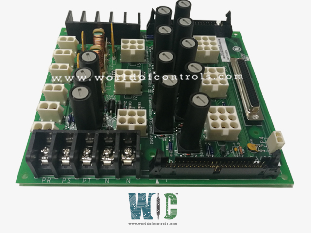
SPECIFICATIONS
Part No.: IS200JPDMG1A
Manufacturer: General Electric
Country of Manufacture: United States of America (USA)
Temperature: 0 to 60 °C
Temperature: -30oC to +65oC
Agency Approval: Class 1 Division 2 explosive atmosphere
Size: 16.51 cm High x 17.8 cm Wide
Mounting: DIN-rail mounting
Product Type: Power Distribution Board
Availability: In Stock
Series: Mark VIe
Functional Description
IS200JPDMG1A is a power distribution board developed by GE. It is a part of Mark VIe control system. JPDM ensures reliable supply to various components in the system. It receives a 28 V DC input power from external AC/DC or DC/DC converters. It efficiently distributes power to the control system, ensuring consistent and reliable supply to all connected components.
Features
- Fuse Protection: Provides fuse protection for all its outputs, safeguarding against overcurrent and short circuit conditions. This ensures the safety and integrity of the connected devices by preventing damage due to electrical faults.
- Integration with PDM System: Seamlessly integrates into the Power Distribution Module (PDM) system, enhancing its functionality. It provides feedback through the PPDA I/O pack, allowing for monitoring and control of power distribution parameters.
- Multiple Power Buses: Designed to maintain three separate power buses for R, S, and T applications, ensuring isolation and redundancy. Each power bus caters to specific functions or subsystems, minimizing the risk of single-point failures and enhancing system reliability.
- Redundancy Options: Jumpers are available to configure JPDM for redundant power supply configurations. These jumpers allow for the creation of a single bus with redundant supplies, ensuring uninterrupted power delivery even in the event of a failure.
- Board Connectivity:Two adjacent boards can be wired together, facilitating scalability and expansion of the power distribution system. This feature enables the creation of larger power distribution networks to accommodate growing system requirements.
Installation
- Mounting Location: Designed to be base-mounted vertically on a sturdy metal bracket within the cabinet dedicated to the Power Distribution Module (PDM). Ensure that the mounting location provides adequate space and accessibility for wiring and maintenance tasks.
- Bracket Installation: Securely attach the metal bracket to the designated location within the cabinet, ensuring it is firmly anchored to the cabinet structure. Verify that the bracket provides sufficient support to hold securely in place during operation.
- Wiring Connections: Refer to the provided wiring diagrams for clear guidance on connecting power inputs and outputs to the JPDM. Follow the specified wiring configurations to ensure proper distribution of power to the control system components.
- Diagnostic Connector Installation: Locate the 50-pin diagnostic connector, labeled as P1/P2, mounted on both the top and bottom of the board. Ensure that these connectors are securely attached to their respective mounting points on the JPDM board.
- Cable Management: Organize and route cables neatly to prevent tangling and interference with other components within the cabinet. Utilize cable ties or clamps to secure cables in place and minimize the risk of accidental disconnection.
- Verification: Before powering on the system, double-check all connections to ensure they are properly seated and secured. Verify that the JPDM is mounted securely on the metal bracket and that all components are aligned correctly.
- Testing: Once installation is complete, perform thorough testing to verify the functionality of the JPDM and its connections. Test each power output to ensure proper voltage levels and continuity.
Outputs
- Outputs J1-J3: These connections are designated for either JPDP or JPDL boards. Each circuit is protected by a 10 A, 250 V fuse, typically a Bussmann MDA-10 fuse. These fuses safeguard the connected boards from overcurrent conditions, ensuring their safe operation.
- Connections JCR, JCS, JCT: These connections are intended for controller power. Each circuit is equipped with a 10 A, 250 V fuse, typically a Bussmann MDA-10 fuse. These fuses provide protection against overcurrent situations, safeguarding the controller power supply.
- Connections JAR, JAS, JAT: These connections are filtered and fused, intended for auxiliary devices. Each circuit is protected by a 3.75 A self-resetting fuse. Self-resetting fuses offer automatic protection against overcurrent events, allowing for uninterrupted operation of auxiliary devices.
- P4 Connection: The P4 connection is designated for PPDA (Power Diagnostic Pack) I/O pack power. The maximum allowable current for this connection is 0.25 A. This connection provides power to the PPDA I/O pack, facilitating its operation within the system.
- JA1 Connection: The JA1 connection is intended for PPDA power diagnostic pack. It provides a maximum voltage of ±5 V for the power diagnostic pack. This connection is crucial for powering and operating the PPDA power diagnostic pack, enabling diagnostic functions within the system.
The WOC team is always available to help you with your Mark VIe requirements. For more information, please contact WOC.
Frequently Asked Questions
What is IS200JPDMG1A?
It is a Power Distribution Board developed by GE under the Mark VIe series.
What distinguishes the feedback wiring on JPDS and JPDM from other PDM core boards?
The feedback wiring on JPDS and JPDM differs from other PDM core boards due to their unique configurations and functionalities. Specifically, the feedback wiring on JPDS and JPDM is optimized to accommodate the PPDA I/O pack.
Can one JPDS or JPDM host the PPDA I/O pack?
Yes, one JPDS or JPDM board can host the PPDA I/O pack using the JA1 connector. This configuration allows for direct connection of output signals to the PPDA without utilizing the P1 connector.
How is the feedback wiring configured when hosting the PPDA I/O pack?
When hosting the PPDA I/O pack, the P1 connector is not used. Instead, the output signals are directly routed to the PPDA. In this configuration, the P2 connector still provides feedback signals from other core PDM boards.
