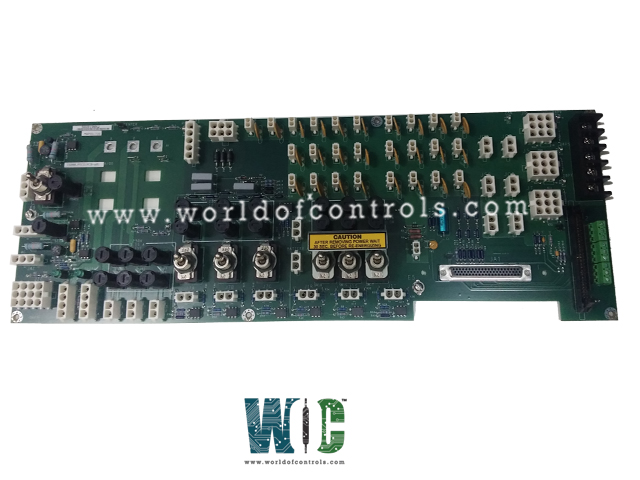
SPECIFICATIONS
Part No.: IS200JPDCG1ACB
Manufacturer: General Electric
Country of Manufacture: United States of America (USA)
Temperature Operating: 0 to 60 oC
Technology: Surface-mount
Board Size: 6.75 in x 19.0 in
Module Size:7.0 in. x 20.4 in. x 3 in.
Mounting: Back-panel mounting
Product Type: Power Distribution Module
Availability: In Stock
Series: Mark VIe
Functional Description
IS200JPDCG1ACB is a Power Distribution Module developed by GE. It is a part of the Mark VIe series. Power Distribution Module integrates input and output functions from multiple previous designs, facilitating the distribution of various voltage levels, including 125 V DC, 115/230 V AC, and 28 V DC, to other boards within a turbine control system.
Installation
- Mounting Orientation: The module is typically mounted vertically, with the 115/230 V AC input connector (JAC) positioned at the bottom.
- Attachment: Secure the module with four screws. Use the mounting holes located at the top and bottom of the module base to attach it firmly.
- Location within the Control Cabinet: While the exact location of the JPDC within the control cabinet is not critical, distribution boards are usually mounted low in the cabinet. This positioning facilitates proper grounding. Refer to the section on Grounding for detailed instructions.
- Optional PPDA I/O Pack: If you are using the optional I/O pack, plug it into connector JA1. Secure the PPDA I/O pack to the base using an angle bracket. The bracket is held in place with nuts threaded onto studs that are permanently attached to the base.
- Diagnostic Feedback Inputs: Connect diagnostic feedback inputs from other distribution boards through a 50-pin ribbon cable. Attach this cable to connector P2.
Physical Arrangement
- Board Dimensions: The module features a 6.75 x 19.0-inch board. This size allows for the integration of multiple components and circuits necessary for power distribution and diagnostic feedback.
- Component Mounting: The board is mounted on a sturdy steel base to provide structural support and durability. Additionally, the module includes a diode assembly and two resistors. These components are strategically positioned on the steel base to optimize their performance and accessibility.
- Voltage Level Distribution: The voltage levels on the JPDC board are arranged to increase from top to bottom, ensuring a logical and safe distribution of power:
- 28 V DC Circuits: Located at the top and left side of the board. This placement allows for easy access to the lower voltage circuits and ensures that they are isolated from the higher voltage areas.
- 125 V DC Circuits: Positioned in the center and right side of the board. This central location allows for a balanced distribution of the mid-level voltage circuits.
- 115/230 V AC Circuits: Found at the bottom of the board. Placing the highest voltage circuits at the bottom helps in maintaining safety and compliance with electrical standards.
Diagnostic Feedback Signals
- FDBK_A2 complements FDBK_A1 by monitoring the attenuated voltage difference between the Negative DC (NDC) bus and ground. Operating in the opposite phase to FDBK_A1, its voltage represents approximately -3.33 percent of the actual NDC bus to ground voltage difference. This signal is critical for ensuring proper grounding and system stability within the turbine control environment.
- FDBK_A3 and FDBK_A4 aggregate multiplexed feedback from connectors J1S-T and J7A-C. These signals require the use of the PPDA I/O pack for decoding, as they are transmitted over the same channel. Demultiplexing is essential to retrieve individual feedbacks accurately from J1S-T and J7A-C, enhancing diagnostic precision and enabling targeted maintenance actions.
- FDBK_A5 focuses on the attenuated AC input voltage, offering a scaled representation at approximately 1.885 percent of the actual AC input voltage. This signal facilitates real-time monitoring of input power conditions, ensuring the module operates within specified voltage parameters critical for system stability and performance.
- FDBK_B1 consolidates multiplexed feedbacks from Battery 1 and Battery 2 inputs, as well as JAC1 and JAC2 outputs. Similar to FDBK_A3 and FDBK_A4, this signal requires the PPDA I/O pack for accurate interpretation. Demultiplexing these inputs is necessary to access individual feedbacks from Battery 1, Battery 2, JAC1, and JAC2, enabling comprehensive system analysis and proactive maintenance to uphold operational reliability.
- These diagnostic feedback signals collectively play a vital role in ensuring the Power Distribution Module operates efficiently within turbine control systems. By providing detailed insights into voltage differentials, system inputs, and multiplexed feedbacks, they empower maintenance personnel to proactively monitor, diagnose, and address potential issues, thereby optimizing system performance and reliability in industrial environments.
The WOC team is always available to help you with your Mark VIe requirements. For more information, please contact WOC.
Frequently Asked Questions
What is IS200JPDCG1ACB?
It is a power distribution module developed by GE under the Mark VIe series.
What is the PPDA I/O Pack?
The I/O pack is a module that collects and processes various power distribution feedback signals. It mounts directly on the JPDC and communicates this information to the IONet.
How does the PPDA I/O Pack connect to JPDC?
The I/O pack mounts directly, utilizing connectors to interface with the power distribution system and gather feedback signals.
What are the feedback signal groups on the I/O Pack connector?
The feedback signals are grouped into two main categories. These groups comprise ten diagnostic signals that monitor and report on the power distribution status.
