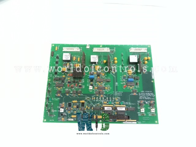
World Of Controls understands the criticality of your requirement and works towards reducing the lead time as much as possible.
IS200GDDDG1A - Gate Driver and Dynamic Discharge Board is available in stock which ships the same day.
IS200GDDDG1A - Gate Driver and Dynamic Discharge Board comes in UNUSED as well as REBUILT condition.
To avail our best deals for IS200GDDDG1A - Gate Driver and Dynamic Discharge Board, contact us and we will get back to you within 24 hours.
SPECIFICATIONS:
Part Number: IS200GDDDG1A
Manufacturer: General Electric
Series: EX2000
Product Type: Gate Driver and Dynamic Discharge Board
Power Supply Voltage: 24 V dc
Power Consumption: 10-20W
Overcurrent Protection: 1.5A to 5A
Gate Drive Voltage: Typically 15V
Supply Voltage Range: 20V to 30V DC
Operating Temperature: -40°C to +85°C
Dimensions: 17.8 cm wide x 33.02 cm
Availability: In Stock
Product of Origin: U.S.A
Manual: GEI - 100241
FUNCTIONAL DESCRIPTION:
IS200GDDDG1A is a Gate Driver and Dynamic Discharge Board manufactured and designed by General Electric as part of the EX2000 series used in excitation control systems. The IS200GDDD Gate Driver and Dynamic Discharge board provide the interface isolation between the IGBTs and the main processor firing circuits of the EX2000 PWM-based exciter. Dynamic discharge circuit control is implemented on the GDDD board as well as the gating circuits for the A-leg and B-leg active IGBTs. The board also provides the instrumentation of the EX2000 PWM. Output dc voltage, dc-link voltage, shunt current mv input, and the heat sink thermistor input are processed on the GDDD board and sent to the LDCC processors for use by the regulators.
JUMPERS:
LEDS:
PLUG CONNECTORS:
WOC has the largest stock of OEM replacement parts for GE Excitation Turbine Control systems. We can also repair your faulty boards and supply unused and rebuilt boards backed up with a warranty. Our team of experts is available round the clock to support your OEM needs. Our team of experts at WOC is happy to assist you with any of your automation requirements. For pricing and availability on any parts and repairs, kindly contact our team by phone or email.
How many test points are available within the assembly, and what do they monitor?
There are eight test points available within the assembly, each serving a unique monitoring function. These test points include analog signals proportional to PWM output voltage and current, DC link voltage, as well as specific signals related to dynamic discharge operations and PWM bridge DC output voltage.
How can technicians use analog TP1 and TP2 to assess the performance of the PWM bridge?
Analog TP1 provides a voltage signal proportional to the PWM output voltage, while Analog TP2 offers a signal proportional to the output current of the PWM bridge. Technicians can use these test points to monitor and analyze the voltage and current levels, aiding in performance optimization and fault detection of the PWM bridge.
How do TP7 and TP8 provide access to the PWM bridge DC output voltage?
TP7 and TP8, when combined, offer access to the PWM bridge DC output voltage. Technicians can use these test points to monitor the voltage output accurately, enabling comprehensive analysis and troubleshooting of voltage-related issues within the system.
Why are monitoring dynamic discharge commands and feedback values important?
Monitoring dynamic discharge command and feedback values (TP5 and TP6) allows technicians to assess the effectiveness of dynamic discharge operations. By comparing these values, operators can ensure proper control over discharge processes, enhancing system performance and safety.