SPECIFICATIONS
Part No.: IS200EXTBG1A
Manufacturer: General Electric
Country of Manufacture: United States(USA)
Product Type: Terminal Board
Series: EX2100e
IS200EXTBG1A is an Exciter Terminal Board developed by General Electric. Pilot relays for the dc contactor or breaker, de-excitation, and field flashing are all supported by the Exciter Terminal Board. There are four types of boards; the EXTBG1 and G3 boards are only used in redundant control, while the EXTBG2 and G4 boards are only used in simplex control. These are connected to the EMIO boards.
IS200EXTBG1A Functional Description
On the board are pilot relays for the close and flashing relays 41, 53A, and 53B, as well as pilot relays for the trip relay 41T and the de-excitation relay KDEP. The EDEX board's crowbar and de-excitation status signals are conditioned on EXTB and sent to EMIO. On EXTB, three contact inputs from 41, 53A, and 53B are powered by 70 V dc and their feedback is monitored. The contacts are powered by the exciter power supply. The status signals generated are sent to the EMIO.
IS200EXTBG1A Relay Control
Pilot Relays
- EXTBG2/G4 controls two flashing relays and the close function relay for simplex control.
- The pilot relays on EXTB are powered by the M1 controller's 24 V dc. Please see Figure 1. One pilot relay with two series contacts drives each flashing relay. Each EXTB contains one 41 close function pilot relay driver that is controlled by an EMIO driver. Before energizing the relay coil, this EMIO driver requires a command from the Field Programmable Gate Array (FPGA) and the 86G contact to be closed. The coil can be de-energized by either the FPGA or the 86G contact.
- The 41 pilot relay employs two parallel contacts. EXTBG1/three G3's inputs from controllers M1, M2, and C control three relays connected in a 2-out of-3 contact voting circuit for redundant control. The relay coil is powered by 24 V dc, and the relays are powered by M1 and M2.
Trip Relay Output
- EXTBG2/G4 controls one trip relay output for simplex control (41T).
- The relay coil is powered by the M1 controller's 24 V dc. Two parallel contacts are used, each with a nominal 125 V dc supplied by the exciter control. EXTBG1/three G3's inputs from controllers M1, M2, and C control three relays connected in a 2-out-of-3 contact voting circuit for redundant control.
De-excitation Pilot Relay (KDEP)
- For redundant control, de-excitation status is supplied to EMIO-M1 and EMIO-M2, and EMIO-M1 for simplex control. The status starts on the EDEX, goes through the conditioning circuit on the EXTBG1/G3 redundant system or the EXTBG2/G4 simplex system, and ends on the EMIO cards. When the 41 or 41T relay is deactivated, the KDEP becomes active immediately.
- On the EXTB, one KDEP is provided, and the circuitry is the same for the redundant and simplex systems. KDEP is powered by 125 volts direct current. The KDEP can be wire jumpered to work with either the 41 relay (Contactor Mode EXTBG1/G2) or the 41T relay (Breaker Mode EXTBG3/G4). The wire jumper position is determined by selecting the appropriate EXTB group.
De-excitation Conditioning Circuit
- The conditioning circuit on EXTB monitors both inputs from the EDEX board in the simplex control, and if either input transitions, the conditioning circuit outputs to EMIO in M1.
- De-excitation signals from two EDEX are supplied to EMIO-M1 and EMIO-M2 via EXTB in the redundant control. EXTB has two signal conditioning circuits, one for each signal. The signal is repeated to EMIO by the EXTB.
Application Data
- The close function pilot relays are K41 (M1, M2, C). The trip pilot relays are K41T, and the flashing pilot relays are K53A and K53B. The single de-excitation pilot relay is KDEP.
- J505, J508, and J515 are 25-pin sub-D connectors for cables to the EMIO boards M1, M2, and C. They carry similar signals and have similar wiring, with the exception that J505 is connected to M1, J508 is connected to M2, and J515 is connected to C.
- However, J515 lacks de-excitation and crowbar signals. For auxiliary contact wetting, plugs J12M1 and J12M2 bring in 70 V dc from the M1 and M2 power supplies.
IS200EXTBG1A Features
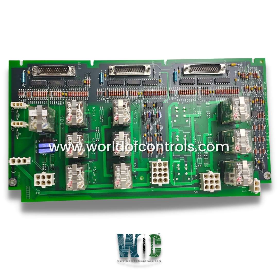
- On the surface of the board are 10 relays. The board is designed to accommodate up to thirteen relays, but the other three spots (marked on the board) remain empty. These relays are labeled for use with M1 or M2 power sources, or with C.
- In addition, the board features seven female plugs of varying sizes. Capacitors might be box capacitors, ceramic capacitors, or electrolytic capacitors. CCRs or metal film are commonly used as resistors. Some locations are designated for components utilized in previous versions of this board but are still empty.
- The PCB is comprised of nine integrated circuits and two conduction sensors. G1 boards are commonly used in contactor mode for redundant control. Refer to our G3 boards if you require redundant control in breaker mode. G2 and G4 boards are used for simplex control.
WOC Team is always available to assist you with your Mark VI needs. Please contact WOC for further details.
Frequently Asked Questions
What is IS200EXTBG1A?
IS200EXTBG1A is a Terminal Board developed by General Electric.
What is the function of the component?
The component is used for field flashing and protection features in EX2100 excitation modules.
How to Obtain IS200EXTBG1A?
World of Controls provides EX2100e as well as other turbine control products. Contact WOC.
