SPECIFICATIONS
Part No.: IS200ESELH2AA
Manufacturer: General Electric
Country of Manufacture: United States of America (USA)
Temperature: -30 to +65oC
Size: 3.175 cm high x 12.7 cm wide
Product Type: Exciter Selector Board
Availability: In Stock
Series: EX2100
Functional Description
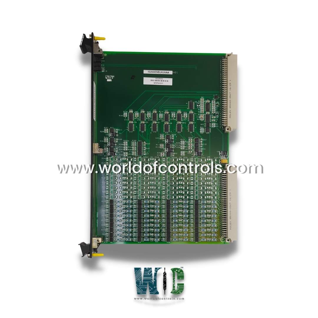
IS200ESELH2AA is an Exciter Selector Board developed by GE. It is a part of the EX2100 excitation system. The Exciter Selector Board facilitates the distribution and management of gate pulse signals essential for the operation of power conversion systems. The Exciter Selector Board is seamlessly integrated into the control rack, providing a centralized hub for processing gate pulse signals. Mounted securely within the rack, it serves as a key interface between the control system and the excitation circuitry.
Features
- Gate Pulse Signal Processing: The board receives six logic-level gate pulse signals from its corresponding master I/O (EMIO) board, a crucial element of the control system architecture. These gate pulse signals are vital for regulating the operation of power conversion systems, and controlling the timing and magnitude of electrical pulses sent to the excitation circuitry.
- Distribution to Exciter Gate Pulse Amplifiers (EGPA): Upon receiving the gate pulse signals, the board orchestrates their distribution to six sets of cables, each connected to an Exciter Gate Pulse Amplifier (EGPA) board. These EGPA boards are strategically mounted within the Power Conversion Cabinet, forming an integral part of the excitation system.
- Bridge Driver Control: Contains three bridge drivers responsible for controlling three Pulse Control Modules (PCM). These bridge drivers play a critical role in modulating the output signals sent to the PCMs, ensuring precise control and coordination of the excitation process.
- Coordination and Synchronization: By effectively managing the gate pulse signals and coordinating their distribution to the EGPA boards, the Exciter Selector Board ensures synchronized operation of the excitation system. This synchronization is crucial for maintaining stability, efficiency, and reliability in power conversion processes.
- Enhanced System Performance: Through its efficient handling of gate pulse signals and precise control over the excitation process, the Exciter Selector Board contributes to enhanced system performance and operational efficiency. By accurately regulating the timing and amplitude of pulse signals, it helps optimize the operation of power conversion systems, maximizing energy conversion efficiency and minimizing downtime.
Application Data
- Absence of Jumpers and Test Points: The Exciter Selector Board (ESEL) is characterized by its simplicity and reliability, with no jumpers or test points present on the board. This streamlined design minimizes complexity and potential points of failure, ensuring robust operation and ease of maintenance.
- Connector Configuration: Connectors P1 and P2 on the board establish connections to the VME backplane, facilitating communication and integration within the system architecture. While the individual pin signals of these connectors are not explicitly defined in the documentation, they serve essential functions in the operation of the board and its interaction with other system components.
- Front Panel Layout: The front panel of the board features three green LEDs positioned at the top, providing valuable status information to system operators and technicians. These LEDs serve as visual indicators of the board's operational state, offering real-time feedback on key parameters.
LED Status Information
- Power On Indicator: This LED illuminates to indicate that power is supplied to the board, providing a visual confirmation of the board's electrical connectivity and readiness for operation.
- Active Board Indicator: The second LED signals the active status of the board, indicating that it has been enabled by the control signal C. This serves as a visual confirmation that the board is operational and ready to receive commands or inputs from the control system.
- Gating Indicator: The third LED denotes the gating status of the board, signifying that it is actively gating or modulating the gate inputs received from the EMIO (master I/O) board. This LED provides crucial feedback on the board's operational mode and its role in controlling the excitation process.
The WOC team is always available to help you with your EX2100 requirements. For more information, please contact WOC.
Frequently Asked Questions
What is IS200ESELH2AA?
It is an exciter selector board developed by GE under the EX2100 series.
How do I prepare the exciter for removal of the ESEL board?
To ensure safety, it's crucial to de-energize the exciter before proceeding with the removal of the board. This involves shutting down power to the exciter to prevent any electrical hazards during maintenance.
What should I check before removing the board from the control rack?
Before proceeding, open the control cabinet door and verify that the power indicators on the EPDM and EPSM power supplies are off. Additionally, ensure that the three LEDs on the board are also off, indicating that it is not actively powered or in operation.
How do I physically remove the board from the control rack?
Loosen the screws located at the top and bottom of the board's faceplate, near the ejector tabs. These screws are captive and should not be removed completely. Raise the ejector tabs to unseat the board from the rack. Using hands, gently pull the board from the rack, taking care to avoid any unnecessary force or damage to the components.
