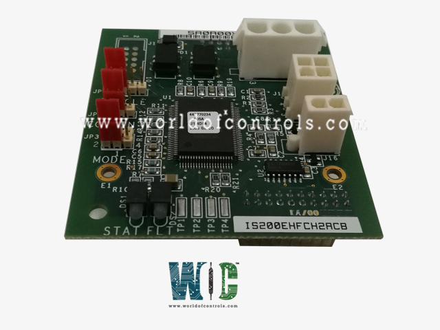
World Of Controls understands the criticality of your requirement and works towards reducing the lead time as much as possible.
IS200EHFCH2A - Thyristor Control Fan Controller Board is available in stock which ships the same day.
IS200EHFCH2A - Thyristor Control Fan Controller Board comes in UNUSED as well as REBUILT condition.
To avail our best deals for IS200EHFCH2A - Thyristor Control Fan Controller Board, contact us and we will get back to you within 24 hours.
SPECIFICATIONS:
Part No: IS200EHFCH2A
Manufacturer: General Electric
Product Type: 100 mm Thyristor Control Fan Controller Board
Series: EX2100
Operating temperature: -30 to 65 ºC
Power Supply Voltage: 24 V dc
Board Size: 2.8 cm high x 8.6 cm
Weight: 0.46 kg
Availability: In Stock
Country of Origin: USA
Manual: GEI-100548
FUNCTIONAL DESCRIPTION:
IS200EHFCH2A is a Thyristor Control Fan Controller Board manufactured and designed by General Electric as part of the EX2100 Series used in Excitation Control Systems. When using the Gate Pulse Amplifier (EHPA) board for EX2100 TM 100 mm Thyristor Control applications, the IS200EHFCG1A Fan Control (EHFC) board is an optional board that mounts to the EHPA board. Each power converter in the 100 mm range has an EHPA near the top front of the device. There could be two, three, or four power converters, depending on the unique application. On the top of each power converter, there are also one or two cooling fans. One fan can be provided for the lowest possible price. However, the generator does not go out when this fan fails; it only affects the power converter part. In order to maintain a full output rating even when one power converter section is down, the 100 mm thyristor control can be equipped with n+1 or n+2 power converter redundancy.
Additionally, two fans per power converter section can be included with the 100 mm thyristor control. This design offers redundancy at the fan level because either fan can run at full converter rating. It won't have an impact on the output of that power converter section if either fan fails and can be replaced online.
All 100 mm thyristor control applications that have two fans per power converter section are supplied with the EHFC, which typically controls the two fans in a lead/lag fashion. One fan, known as the active (lead) fan in lead/lag control, cools the power converter. In order to ensure proper cooling, the backup (lag) fan is turned on if the lead fan fails. The following functionalities are offered by EHFC in its standard features:
APPLICATION DATA:
Detailed information about EHFC interfaces, configuration, diagnostics, and operating behavior is provided in this area. View the arrangement of the EHFC board's important parts, including mounting holes, connectors, configuration jumpers, and indication lights, in the figure below.
JUMPERS:
The jumpers on the EHFC are configured as shown in the tables below. EHPA jumper JP2 (NCMODE) operation also has an impact on EHFC. The Hall effect speed sensor can be replaced with a normally closed contact input by using this jumper. The Hall effect sensor is used in all EX2100 applications, and JP2 should be at the default 1-2 position. For further information on EHPA, see GEI-100532.
OPERATION:
Never turn on both fans at the same time. To lessen the demand on the fan power supply during startup, there is always a minimum five-second wait between closing the starters. Unless JP2 is configured for continuous operation, the fans do not automatically turn on at power-up. The SCR bridge's gating or a Transfer instruction are the only other circumstances that will cause the fans to turn on. The lag fan is started and tested first when the Transfer button is momentarily depressed, assuming lead/lag mode. The fan is given five seconds to start spinning. If not, an alarm is signaled and transmitted to the control. The lead fan starts and is tested after five seconds, followed by another five seconds. The fans will be turned off at the conclusion of the test unless JP2 is configured for continuous operation or the bridge temperature is more than 50 °C (122 °F). If both fans passed the test, the lead/lag designations are switched, and the new lag fan will start first on the following Start or Transfer.
The fan starting procedure is similar to what was described before if the exciter is started in order to gate the bridge. The lag fan or fan 2 in dual mode begins first and is tested. The lead fan (or fan 1) is then turned on and put to the test. If the lead fan starts in lead/lag mode, the lag fan will cease after ten seconds. The lag fan continues to run even if the lead fan cannot start. The control receives reports of fan failures. After the test, dual mode requires both fans to keep operating. Fan 1 needs to operate in single mode. Either fan operating is sufficient in lead/lag mode. In the absence of this, the bridge will close in roughly 20 seconds.
WOC has the largest stock of GE Excitation Control replacement spare parts. We can repair your faulty boards. WORLD OF CONTROLS can also supply unused and rebuilt backed-up with a warranty. Our team of experts is available round the clock to support your OEM needs. Our team of experts at WOC is happy to assist you with any of your automation requirements. For pricing and availability on any parts and repairs, kindly get in touch with our team by phone or email.
FREQUENTLY ASKED QUESTIONS:
How to Check Price and Availability For IS200EHFCH2A?
Please Contact World of Controls FZE for sales at +1 609 385 1231 or Request a Quote.
How are boards packaged for shipment from WOC?
Parts are placed in antistatic packets and securely packed in ESD boxes cushioned with ESD Foam designed to safeguard electrical components.
What Payment Options do You Accept?
Bank Transfer is the preferred payment method. For more payment options contact us.