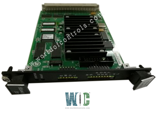
World Of Controls understands the criticality of your requirement and works towards reducing the lead time as much as possible.
IS200DSPXH2C - Digital Signal Processor Control Board is available in stock which ships the same day.
IS200DSPXH2C - Digital Signal Processor Control Board comes in UNUSED as well as REBUILT condition.
To avail our best deals for IS200DSPXH2C - Digital Signal Processor Control Board, contact us and we will get back to you within 24 hours.
SPECIFICATIONS:
Part Number: IS200DSPXH2C
Manufacturer: General Electric
Series: Innovation
Product Type: Digital Signal Processor Control Board
Number of channels: 12
Max load Current: 125 V dc
Outputs: 24 V dc
Voltage Range: 14 to 32 V dc
Maximum Lead Resistance: 15 Ω
Outputs: 24 V dc
Mounting: DIN-rail mounting
Technology: Surface mount
Operating temperature: -30 to 65°C
Size: 15.9 cm high x 17.8 cm
Repair: 3-7 Day
Availability: In Stock
Weight: 2 lbs
Country of Origin: United States
Manual: GEI-100267B
FUNCTIONAL DESCRIPTION:
IS200DSPXH2C is a Digital Signal Processor Control Board manufactured and designed by General Electric as part of the EX2100 Series used in GE Drive Control Systems. The IS200DSPX Digital Signal Processor Control Board (DSPX) is the primary controller for the bridge and motor regulator and gating functions for Innovation Series drives. It also controls generator field control functions for the EX2100e Excitation Control. The board provides logic, processing, and interface functions. The DSPX board includes a high-performance digital signal processor (DSP), standard memory components, and an application-specific integrated circuit (ASIC) that performs custom logic functions.
WOC has the largest stock of GE Drive Control System Replacement Parts. We can also repair your faulty boards. WORLD OF CONTROLS can also supply unused and rebuilt backed-up with a warranty. Our team of experts is available round the clock to support your OEM needs. Our team of experts at WOC is happy to assist you with any of your automation requirements. For pricing and availability on any parts and repairs, kindly get in touch with our team by phone or email.
What is a Digital Signal Processor (DSP) Control Board?
A DSP Control Board is a hardware device containing a Digital Signal Processor (DSP) chip. It is designed to process digital signals in real time for various applications such as audio processing, telecommunications, and control systems.
What are the primary functions of a DSP Control Board?
The primary functions of a DSP Control Board include signal processing tasks such as filtering, modulation, demodulation, encoding, decoding, and digital control algorithms implementation. It also handles interfacing with other system components and executing control logic.
How are boards packaged for shipment from WOC?
Parts are placed in antistatic packets and securely packed in ESD boxes cushioned with ESD Foam designed to safeguard electrical components.