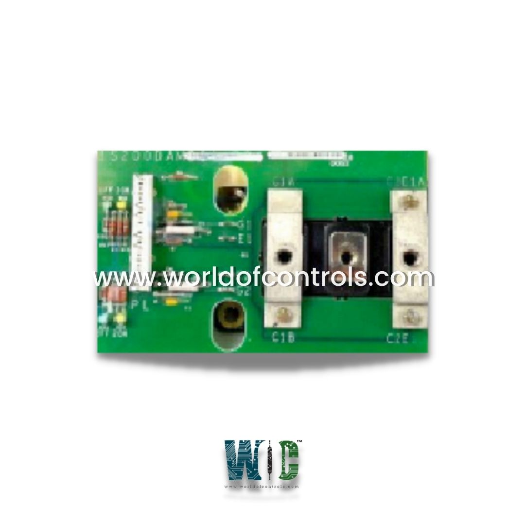
World Of Controls understands the criticality of your requirement and works towards reducing the lead time as much as possible.
IS200DAMDG2A - Gate Drive Interface Board is available in stock which ships the same day.
IS200DAMDG2A - Gate Drive Interface Board comes in UNUSED as well as REBUILT condition.
To avail our best deals for IS200DAMDG2A - Gate Drive Interface Board, contact us and we will get back to you within 24 hours.
SPECIFICATIONS:
Part Number: IS200DAMDG2A
Manufacturer: General Electric
Function: Gate Drive Interface Board
Frame Rate: 125
Power supply input: +15/-7.5
Powerrex IGBT: CM200DY-28H
Power rating: 92 frames or 125 frames
LED indicators: DS1, DS2, DS3, and DS4
Product type: PCB
No.of board/drive: 3
IGBT/phase leg: One dual
Series: Drive Control
Availability: In Stock
Country of Manufacture: United States (USA)
Manual: GEI-100267B
FUNCTIONAL DESCRIPTION:
IS200DAMDG2A is a Gate Drive Interface Board manufactured and designed by General Electric as part of the Mark VI Series used in GE Drive Control Systems. The function of the Gate Drive Interface Board is to amplify the gate signals that control the power switches and to interface with the control system of the machinery. This board operates at a Frame Rate of 125, which refers to the frequency at which the board can send signals to the machinery. The Powerrex IGBT used in this board is the CM200DY-28H. The board comes with three board/drive units, which means that three separate units can be used to control different aspects of the machinery. The IGBT/phase leg configuration for each unit is one dual, which means that each unit contains one dual IGBT that controls one phase leg of the machinery. The Digital Amplifier Module board is a type of circuit board that serves as an interface between power-switching devices, specifically Insulated Gate Bipolar Transistors, and the control rack in low-voltage drives.
FEATURES:
Interface Between Power Switching Devices and Control Rack: Serves as a crucial interface between the power switching devices, such as IGBTs, and the control rack in low voltage drives. This interface enables seamless communication and control signals between the control system and the power-switching devices, ensuring proper operation and synchronization.
Power Rating: The board is designed with a power rating of either 125 frames or 92 frames. This power rating indicates the board's capacity to handle and regulate power within the low-voltage drive system. It ensures that the board can effectively handle the power demands of the connected IGBTs and facilitate efficient power switching operations.
Non-Amplifying Interface: Do not amplify power and do not require a power input. They function solely as an interface, connecting the collector terminals, emitter, and IGBT gate of the power switching devices to the BPIA Bridge Personality Interface board of the control rack. This non-amplifying nature allows for a direct and reliable connection without introducing additional amplification stages.
Absence of Fuses, Test Points, and Configurable Items: Do not include fuses, test points, or configurable items. These boards are specifically designed to provide a clean and straightforward interface without additional components or options. This simplifies the board's design and ensures its dedicated functionality as an interface module.
Dual-IGBT Module per Phase Leg: Equipped with one dual-IGBT module. This module consists of two IGBTs and supports the precise control and switching of power within the low-voltage drive system. The presence of a dual-IGBT module allows for efficient and coordinated power-switching operations.
Light-Emitting Diodes (LEDs): Incorporates four light-emitting diodes (LEDs) to provide visual feedback on the system's status. Two LEDs are yellow, and the other two are green. These LEDs are labeled DS1 (yellow), DS2 (green), DS3 (yellow), and DS4 (green) and are further identified as 1ON, 1FF, 2ON, and 2FF, respectively. These LEDs serve as indicators for different operating conditions, providing users with real-time feedback on the status of the board and the connected components.
Connector Pins for IGBT Connections: Features twelve connector pins that are specifically designed for IGBT connections. These pins include G2IN, COM2, NC, C2, COM1, G1IN, and C1. These pins ensure secure and reliable connections between the board and the IGBTs, facilitating proper signal transmission and control over the power switching devices.
Compact and Attachable Design: Small in size and shaped like the letter C. This compact design allows for easy integration and installation within the low-voltage drive system. Furthermore, if needed, these boards can be attached to larger boards, providing flexibility in system configuration and expansion possibilities.
WOC has the largest stock of GE Drive Control System Replacement Parts. We can also repair your faulty boards. WORLD OF CONTROLS can also supply unused and rebuilt backed-up with a warranty. Our team of experts is available round the clock to support your OEM needs. Our team of experts at WOC is happy to assist you with any of your automation requirements. For pricing and availability on any parts and repairs, kindly get in touch with our team by phone or email.
What is a Gate Drive Interface Board (GDIB)?
A Gate Drive Interface Board (GDIB) is a circuit board designed to interface between control electronics and power electronic devices, such as power transistors or insulated gate bipolar transistors (IGBTs). It provides the necessary signals and power to drive and control the switching of these devices.
What is the purpose of a Gate Drive Interface Board?
The primary purpose of a GDIB is to ensure the efficient and reliable switching of power devices by providing the required gate drive signals. It acts as an intermediary between low-voltage control circuitry and high-voltage power devices, isolating the control electronics from potentially damaging high voltages.
Why is isolation important in a Gate Drive Interface Board?
Isolation is crucial to prevent voltage spikes and electrical noise from affecting the control circuitry. By using isolation techniques such as optocouplers or transformers, the GDIB ensures that any disturbances in the high-power side do not propagate to the low-power control side, enhancing the overall reliability and safety of the system.