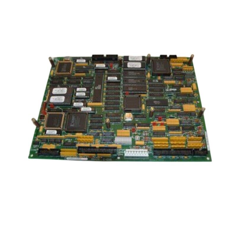
World Of Controls understands the criticality of your requirement and works towards reducing the lead time as much as possible.
IS200DAMBG1A - Gate Driver Board is available in stock which ships the same day.
IS200DAMBG1A - Gate Driver Board comes in UNUSED as well as REBUILT condition.
To avail our best deals for IS200DAMBG1A - Gate Driver Board, contact us and we will get back to you within 24 hours.
SPECIFICATIONS:
Part Number: IS200DAMBG1A
Manufacturer: General Electric
Series: Drive Control
Product Type: Gate Driver Board
Number of channels: 24
Number of relay channels: 12
Power Requirements: +5 V dc, 6 A
Trip Solenoid Rating: 125 V dc
Power supply voltage: 28 V dc
Excitation voltage: 125 Vdc
Voltage Range: 18 - 32 VDC
Mounting: DIN-rail mounting
Technology: Surface mount
Operating temperature: 40 to 70°C
Size: 17.8 cm wide x 33.02 cm
Repair: 3-7 Day
Availability: In Stock
Country of Origin: United States
FUNCTIONAL DESCRIPTION:
IS200DAMBG1A is a Gate Driver Board manufactured and designed by General Electric as part of the Mark VI Series used in GE Drive Control Systems. A gate driver board is an electronic circuit board used to control the switching of power semiconductor devices, such as MOSFETs, IGBTs, or SiC devices. It provides a low voltage signal to the gate of the power device to turn it on or off and is designed to drive the gate capacitance quickly and efficiently. Gate driver boards are commonly used in power electronics applications, such as motor drives, inverters, and power supplies. They are typically designed to provide high-current pulses to the gate of the power device, with fast rise and fall times to minimize switching losses and improve efficiency.
FEATURES:
WOC has the largest stock of OEM replacement parts for GE Drive Control Systems. We can also repair your faulty boards and supply unused and rebuilt boards backed up with a warranty. Our team of experts is available round the clock to support your OEM needs. Our team of experts at WOC is happy to assist you with any of your automation requirements. For pricing and availability on parts and repairs, kindly contact our team by phone or email.
What is the purpose of a gate driver board?
The purpose of a gate driver board is to provide a low-voltage signal to the gate of a power semiconductor device to turn it on or off quickly and efficiently.
What is the maximum frame size of the boards, and how many boards are required per drive?
The maximum frame size of the boards is 620, and three boards are required per drive, one for each phase leg.
How many IGBTs are included and how are they connected?
The module includes one IGBT for the upper phase leg and one IGBT for the lower phase leg, and they are directly connected to the IGBT collector terminals, gates, and terminals, as well as the BPIA Bridge Personality Interface board located within the control rack.