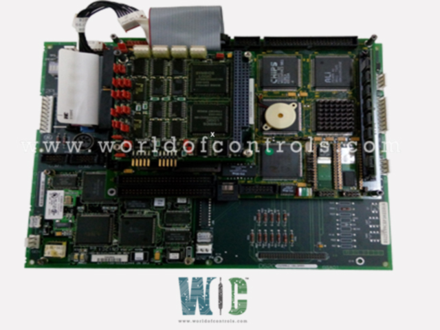
World Of Controls understands the criticality of your requirement and works towards reducing the lead time as much as possible.
DS200UCIBG3A - UC2000, Main Control Card is available in stock which ships the same day.
DS200UCIBG3A - UC2000, Main Control Card comes in UNUSED as well as REBUILT condition.
To avail our best deals for DS200UCIBG3A - UC2000, Main Control Card, contact us and we will get back to you within 24 hours.
SPECIFICATIONS
Part Number: DS200UCIBG3A
Manufacturer: General Electric
Series: Mark V
Product Type: UC2000 Motherboard
Availability: In Stock
Country of Origin: USA
DS200UCIBG3A is a UC2000
The LBC586P has a daughterboard placed on it that houses the PANA board for ARCNET connections. P1. TCSA – Contains decoders for serial communication for Dry Low Emissions (DLE) applications between the XDSA board on the gasoline skid and the UCIB. L2. For Dry Low Emissions (DLE) applications, the Fuel Skid Interface Board (TCSA), located in the R core, communicates with the XDSA board on the fuel skid. For the 196 processors on the UCIB board, the TCSA board decodes the signals from the high-resolution pressure transducers. Position 8 of the R2> core is where the signals from XDSA are connected to the TBSA terminal board. Through the P3 connector, the TCSA board reads them. Decoded pressure transducer signals are written to the UCIB board via SER.
UCIB CONNECTORS
J1 - Bus connector that communicates with the LBC-586 and PANA boards.
J2 - Connector for IDE flash drive.
J3 - Bus connector that communicates with the LBC-586 and PANA boards.
J4 - Routes IDE disk signals between the LBC-586 and UCIB boards.
UCIB CONFIGURATION
Hardware: The clock is enabled by hardware jumper JP1. For details on the hardware jumper settings for this board, consult Appendix A and the operator interface's hardware jumper panel.
Software: The UCIB board has no software configuration.
UCIB PRESSURE TRANSDUCER INTERFACE CIRCUIT
The TBSA terminal board in the R2 core receives the high-resolution pressure transducer signals from the XDSA board. The signals are received by the P3 connector on the TCSA board, which then decodes them for the 196 processor on the UCIB board to use. The J1 and J3 connectors are used to write the signals to the LBC586P board.
UCIB GENIUS I/O CIRCUIT
On the UCIB board, a GENI board may be installed. Certain types of data flow between the host (Mark V LM) and the Genius bus are controlled by a GENI board. On the 1TB terminal board on the "R" core, the Genius bus connections are formed. The signals are written to the LBC586P board via the P5 connector on the UCIB board and passed by the GENI board through the serial connector P3 on the UCIB board. The GENI board is powered by the UCIB board via the P15 connector.
Many connectors on the LBC586P card are not used for the Mark V LM application. The following connections are made to the LBC-586 card:
J26 - Bus connector for processor interface to memory and IO on the UCIB and PANA.
J29 - Bus connector for processor interface to memory and IO on the UCIB and PANA.
J18 - IDE interface connector. Ribbon cable connected to J4 on the UCIB.
J7 - Power cable. Connected to P8 on the UCIB.
J3 - Serial and other miscellaneous signals. Connected to P13 on the UCIB.
WOC supports a large number of GE Speedtronic Mark V Spare parts, including DS200UCIBG3A. Please do not hesitate to contact us if you require additional information or have a question.
FREQUENTLY ASKED QUESTIONS
What is GE Mark V DS200UCIBG3A?
The DS200UCIBG3A is a UC2000 Core Mother Board connector for connecting the host CPU daughterboard, two GENI boards, and a flash drive provided by the R Core Mother Board.
What is an IDE connector?
A motherboard can be connected to storage devices like hard drives using this common interface.
How to Check Price and Availability For DS200UCIBG3A?
Please Contact World of Controls FZE for sales at +1 609 385 1231 or Request a Quote.