SPECIFICATIONS
Part No.: DS200UCIAP1AAC
Manufacturer: General Electric
Country of Manufacture: United States of America (USA)
Temperature Operating: -30 to 65oC
Product Type: UC2000 Motherboard
Availability: In Stock
Series: Drive Control
Functional Description
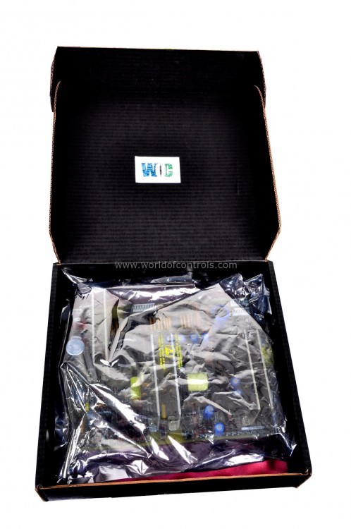
DS200UCIAP1AAC is an UC2000 Motherboard developed by GE. It is a part of the Drive Control series. It serves as the central printed wiring board within the UC2000 system, providing essential connectivity and functionality for various components. This board is pivotal for system operation and integration, featuring a range of connectors and components that facilitate seamless interaction with additional boards and peripherals.
Features
- One of the primary functions is to provide mounting points for additional boards, such as the UCP) and μGENI. These connectors enable easy installation and integration of these boards into the UC2000 system, expanding its capabilities and functionality as needed.
- Within the board, there is a jumper labeled JP1, which is exclusively utilized for factory tests during the manufacturing process. This jumper serves a diagnostic purpose during initial testing stages, ensuring that the board functions correctly before deployment into the system.
- For diagnostic purposes during operational use, the UCIA board features test points, labeled TP1 and TP2. These test points provide access to specific signals or voltage points on the board, allowing technicians to perform diagnostic checks and troubleshoot issues as necessary, as guided by the system's diagnostics protocols.
- Additionally, the board incorporates a set of LEDs designated as DN1, which are defined and controlled by the process software. These LEDs serve as visual indicators, providing status feedback and operational insights to users and technicians, aiding in system monitoring and diagnostics.
- It includes a fan connector labeled P14, which is responsible for supplying 5 V of power to the fan on the UCPB board. While this connection is optional, it contributes to the cooling and temperature management of the UCPB board, ensuring optimal performance and longevity.
Board Replacement
- Ensure Power Off: Before beginning any maintenance or replacement procedure, verify that all power to the unit is turned off. This precautionary step helps prevent electrical hazards during the replacement process.
- Open the Unit Door: Loosen the top middle thumb screw located on the outside of the unit door to open it. The assembly is secured in place by plastic snaps or holders. Gently open the door to access the internal components.
- Disconnect Daughterboards: Prior to removing the UCIA/UCPB assembly from its holder, disconnect any uGENI daughterboard(s) connected to the UCIA. Ensure that all connectors involved are safely disconnected to avoid damage during removal.
- Release UCIA Board: Push the top portion of the board to release it from the holders. Exercise caution to avoid damaging any components. Carefully lift the assembly out from the bottom snaps, ensuring a smooth and steady removal process.
- Install New Assembly: Position the new assembly by aligning the boards with the six plastic standoffs attached to the unit. Carefully seat both ends of the assembly into the holder, ensuring proper alignment and fit. Once aligned, gently press the assembly into place until it securely snaps into position.
- Replace Daughterboards and Reconnect Cables: If the daughterboard(s) were removed in step 3, replace them in their respective slots. Reconnect all cables, ensuring they are properly seated at both ends to establish secure connections. Double-check the connections to ensure proper alignment and fitment.
The WOC team is always available to help you with your drive control requirements. For more information, please contact WOC.
Frequently Asked Questions
What is DS200UCIAP1AAC?
It is an UC2000 Motherboard developed by GE under the Drive Control series.
Why is it necessary to ensure all power to the unit is off before starting the replacement process?
Ensuring all power to the unit is off prevents potential electrical hazards and ensures safety during the replacement process. It reduces the risk of electric shock or damage to components.
How do I access the assembly within the unit?
To access the assembly, you need to open the door of the unit by loosening the top middle thumb screw on the outside of the door. The assembly is held in place by plastic snaps or holders inside the unit.
What precautions should be taken before removing the UCIA/UCPB assembly?
Before removing the UCIA/UCPB assembly, it's essential to disconnect any uGENI daughterboard(s) connected to the UCIA and disconnect all involved connectors. This prevents damage to the components during removal.
How do I release and remove the board?
To release the board, push the top portion of the board to disengage it from the holders. Then, carefully lift the assembly out from the bottom snaps, ensuring a steady and controlled removal process.
