World Of Controls understands the criticality of your requirement and works towards reducing the lead time as much as possible.
DS200UCIAG2A - UC2000 Motherboard is available in stock which ships the same day.
DS200UCIAG2A - UC2000 Motherboard comes in UNUSED as well as REBUILT condition.
To avail our best deals for DS200UCIAG2A - UC2000 Motherboard, contact us and we will get back to you within 24 hours.
SPECIFICATIONS:
Part Number: DS200UCIAG2A
Manufacturer: General Electric
Function: UC2000 Motherboard
Series: EX2000
Power Requirements: +32 V dc to 18 V dc
Operating temperature: 0 to +65°C
Weight: 2 lbs
Availability: In Stock
Country of Origin: USA
Manual: GEI-100198
FUNCTIONAL DESCRIPTION:
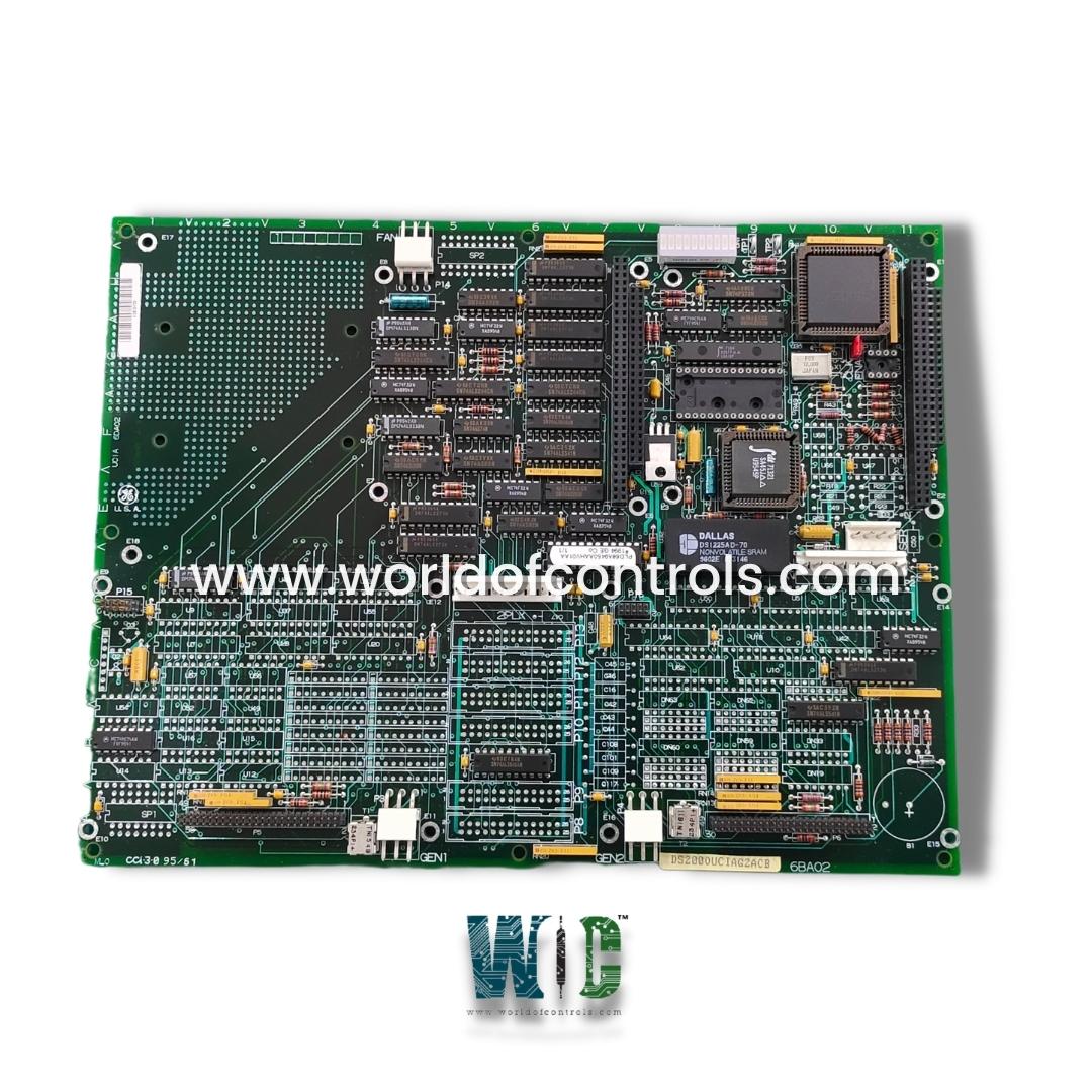
DS200UCIAG2A is a UC2000 Motherboard manufactured and designed by General Electric as part of the EX2000 Series used in GE Excitation turbine control systems. The main printed circuit board in the Innovation Series controller is called the UCIA. It has connectors that allow other boards, including the UCPB and IC660ELB912G (GENI), to be mounted. One jumper, JP1, which is solely used for manufacturing tests, is included on the UCIA board. When the process specifies, test points TP1 and TP2 are used for diagnostics. LEDs chosen by the process software make up DN1. The fan on the UCPB board is powered by 5 V through the fan connector (P14).
It is used to supply the connectors necessary for attaching the UCPB CPU daughter board, the PANA ARCNET no-LAN driver board, up to two GENI boards, and a PDAD hard drive. It is situated on the R core of the EX2000 excitation control system. The fuel skid pressure signals are translated using an onboard 196 microprocessor, which is subsequently utilized to send and write the signals to the UCPB board. The control sequence software then applies these signals. It has numerous vertical and right-angled connectors, a lot of integrated circuits embedded into the board, resistor network arrays, jumper switches, capacitors, and resistors.
Fig 1: UCIA Board Layout
BOARD REPLACEMENT PROCEDURE:
WOC maintains the largest inventory of replacement parts for GE Excitation control systems. Additionally, we offer warranty-backed unused and rebuilt boards as well as board repairs for your damaged ones. For your OEM needs, our team of professionals is available around-the-clock. We at WOC are happy to help you with any needs you may have in terms of automation. Please contact our team by phone or email for pricing and availability on any components and repairs.
FREQUENTLY ASKED QUESTIONS:
What Core does the component belong to?
It is one of six boards in the R core and is located in the R core, sometimes known as the Control Engine core.
How are the boards mounted?
It is the motherboard where the UCPB, PANA, and uGENI boards are mounted.
How to Check Price and Availability For UC2000 Motherboard?
Please Contact World of Controls FZE for sales at +1 609 385 1231 or Request a Quote.
WORLD OF CONTROLS warrants that from the date of delivery for a period of 36 months all UNUSED / REBUILT goods shall conform in all material respects with their description and any applicable specification.
WORLD OF CONTROLS warrants that from the point of delivery all Repairs will accord with their description and/or remain functional subject to the performance of the Repair Item for a period of 24 months.