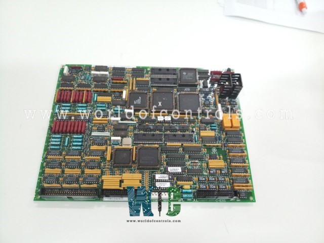
SPECIFICATIONS
Part No.: DS200TCQAG2BHF
Manufacturer: General Electric
Country of Manufacture: United States of America (USA)
Temperature: -30 to + 65oC
Product Type: Analog IO Board
Availability: In Stock
Series: Mark V
Functional Description
DS200TCQAG2BHF is an Analog IO Board developed by GE. It is a part of Mark V control system. The Analog IO Board functions in scaling and conditioning a variety of analog signals that are read by terminal boards mounted on the I/O cores labeled R1, R2, and R3. This board ensures that the signals are properly processed and prepared for further use within the system, maintaining the accuracy and reliability required for industrial applications. Certain input signals, such as the 4-20 mA signals related to fuel flow pressure and compressor stall detection, are specifically scaled and conditioned on the TCQA board. This precise conditioning ensures that these critical measurements are accurate and reliable, which is vital for the safe and efficient operation of the equipment.
Types of Signals Handled
- LVDT Inputs: Linear Variable Differential Transformers (LVDTs) provide precise position feedback. The board conditions these signals to ensure accurate measurement and control.
- Servo Valve Outputs: The board processes signals that control servo valves, which are essential for precise movement and fluid control in hydraulic systems.
- Thermocouple Inputs: Thermocouples measure temperature, and the board conditions these inputs to ensure accurate temperature monitoring and control.
- 4-20 mA Inputs and Outputs: Widely used in industrial control systems, 4-20 mA signals are conditioned by the board for various applications, including monitoring and control of processes.
- Vibration Inputs: Vibration sensors monitor equipment health, and the TCQA board processes these signals to detect abnormalities and prevent failures.
- Relay Driver Outputs: The board manages outputs that drive relays, essential for switching and controlling various electrical circuits.
- Pulse Inputs: Pulse signals, often used for counting and timing applications, are conditioned by the TCQA board for precise measurement.
- Voltage Inputs: The board handles a range of voltage inputs, conditioning them for accurate monitoring and control.
- Generator and Line Signals: The board processes signals related to power generation and distribution, ensuring reliable operation of generator and line systems.
Signal Transmission and Conditioning
- Board via 3PL Connector: Some conditioned signals are written to the board through the 3PL connector, ensuring smooth and accurate data flow between components.
- Board via JE Connector: Generator and line signals are exchanged with the TCQC board via the JE connector, maintaining the integrity and accuracy of power-related signals.
Hardware Configuration
- Jumpers J1 and J2 are utilized to select the mA output circuits. These jumpers determine which circuits are active and control the routing of the mA output signals.
- Jumpers J5 and J6 are employed to configure the mA outputs current range. Users can choose between a maximum output of either 20 mA or 200 mA, depending on the requirements of the application. These jumpers ensure that the mA output signals are scaled appropriately for compatibility with connected devices.
- Jumper J7 is designated for the RS232 port, specifically for card tests. This jumper enables communication via the RS232 port, facilitating diagnostic tests and troubleshooting procedures.
- Jumper J8 serves to enable an oscillator, which may be utilized for specific functions or testing purposes. Enabling the oscillator through J8 provides additional flexibility in configuring the TCQA board for various applications.
Software Configuration
- Thermocouples: Configuration constants for thermocouples define parameters such as type, calibration, and temperature range.
- Pulse Rates: Settings for pulse rates specify the frequency or rate at which pulse signals are generated or monitored.
- Vibrations: Configuration constants for vibrations include parameters related to sensor sensitivity, frequency range, and alarm thresholds.
- LVDT Positions: LVDT position settings define the calibration, range, and resolution of position feedback signals.
- 4.20 mA Inputs and Outputs: Configuration constants for 4-20 mA inputs and outputs determine scaling, calibration, and range settings for these signals, ensuring accurate measurement and control.
The WOC team is always available to help you with your Mark V requirements. For more information, please contact WOC.
Frequently Asked Questions
What is DS200TCQAG2BHF?
It is an analog IO board developed by GE under the Mark V series.
How do I select the mA output circuits using jumpers J1 and J2?
Jumpers J1 and J2 on the board are used to select the active mA output circuits. By configuring these jumpers, users can specify which circuits are utilized for generating mA output signals.
What is the purpose of jumpers J5 and J6 on the board?
Jumpers J5 and J6 are employed to configure the mA output current range. Users can choose between a maximum output of either 20 mA or 200 mA, depending on the requirements of the application.
How can I enable the RS232 port for card tests using jumper J7?
Jumper J7 is designated for enabling the RS232 port specifically for card tests. By configuring this jumper, users can enable communication via the RS232 port, facilitating diagnostic tests and troubleshooting procedures.
