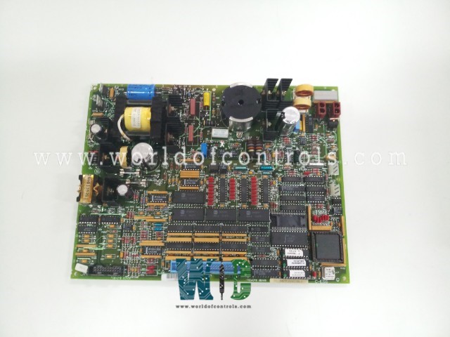
World Of Controls understands the criticality of your requirement and works towards reducing the lead time as much as possible.
DS200TCEAG2BLE - Emergency Overspeed Board is available in stock which ships the same day.
DS200TCEAG2BLE - Emergency Overspeed Board comes in UNUSED as well as REBUILT condition.
To avail our best deals for DS200TCEAG2BLE - Emergency Overspeed Board, contact us and we will get back to you within 24 hours.
Part Number: DS200TCEAG2BLE
Manufacturer: General Electric
Country of Manufacture: United States (USA)
PCB Coating: Normal
Repair: 3-5 Days
Series: Mark V
Function: Emergency Overspeed Board
DS200TCEAG2BLE is an Emergency Overspeed Board developed by GE. It is part of the GE Speedtronic Mark V control system. It is commonly referred to as the Protective Processor and is located within the Protective Core (P1). The TCEA board handles critical safety functions, including turbine overspeed detection, flame detection, and automatic synchronization.
Hardware Configuration
Software Configuration
Flame Detection Circuit
UV flame detectors send signals through the PTBA board, which are then routed to the TCEB board and subsequently to the board. These signals are scaled, conditioned, and analyzed to determine flame presence. The Control Sequence Program (CSP) in the (R) core utilizes these signals, which are also sent to the I/O Engine and Control Engine for monitoring.
Overspeed trip levels are defined through I/O configuration constants and confirmed with hardware jumpers. Magnetic pickups on the PTBA board monitor shaft speed and send data to the (R1) core, while the board calculates shaft speed and compares it to the trip values. If overspeed is detected, the board de-energizes Emergency Trip Relays (ETRs) on the TCTG board to initiate a trip. Jumpers J28 and J29 ensure redundancy, enabling a dual system for emergency trip conditions.
Bus and generator voltage signals from the PTBA board are routed to the TCEB board and then to the board for speed and voltage matching. The TCEA board calculates generator and line voltage/frequency differences to permit breaker closure when conditions are met. An additional synchronization check is performed by the STCA board, which sends a logic signal to the board, completing the synchronization process.
WOC has the largest stock of Mark V Spares and we can repair your faulty spares with a warranty. WORLD OF CONTROLS can also supply unused and rebuilt components backed by a warranty. Our team of experts is available round the clock to support your urgent needs related to critical spares, Contact us.
What is DS200TCEAG2BLE?
It is an Emergency Overspeed Board and is part of the GE Speedtronic Mark V gas turbine control system.
How is emergency overspeed protection achieved?
The board monitors shaft speeds and compares them with configuration constants for overspeed limits. If an overspeed condition is detected, the board will de-energize the Emergency Trip Relays (ETRs) on the Turbine Trip Board (TCTG), initiating a unit trip.
How does the flame detection system work on the board?
UV flame detector signals are routed to the board through the PTBA and TCEB boards. These signals are then scaled, conditioned, and analyzed to determine flame status, which the system uses to support safe operation.
How does the board facilitate automatic synchronization?
The board receives generator and bus voltage data, checks for speed and voltage matching, and issues a breaker-close permissive if conditions are within safe limits. The STCA board also performs a secondary synchronization check for additional safety.