SPECIFICATIONS
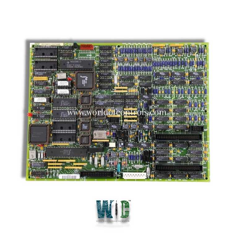
Part No.: DS200TCCBG3ANE
Manufacturer: General Electric
Country of Manufacture: United States of America (USA)
Temperature: -30 to +65oC
Product Type: Common Extended Analog I/O Board
Availability: In Stock
Series: Mark V
Functional Description
DS200TCCBG3ANE is a Common Extended Analog I/O Board developed by GE. It is a part of Mark V control system. The Common Extended Analog I/O Board enhance the analog input and output capabilities of a power generation control system. This board is specifically designed to handle the scaling and conditioning of additional analog I/O signals, ensuring accurate and reliable data processing.
Features
- Interfaces with signals read from two key terminal boards- the terminal board, which is mounted on the R5 core, and the TCEB Board, located in the P1 core. These terminal boards serve as the collection points for various analog input signals that need to be processed by the system. It ensures that these signals are appropriately scaled and conditioned for further use.
- Capable of handling a variety of analog signals, including 4-20 mA inputs, which are commonly used for transmitting sensor data over long distances; 0-1 mA inputs, typically used in specialized instrumentation; RTDs, which are used for precise temperature measurements; generator and bus voltage inputs, for monitoring and controlling electrical power systems; and line current inputs, important for measuring the current flowing through power lines.
- Signal conditioning involves processes such as filtering, amplification, and isolation to ensure that the signals are clean and within the desired range. Scaling adjusts the signal levels to match the requirements of the processing units or control systems. Once the signals have been scaled and conditioned by the TCCB, they are transmitted to the STCA board. This transmission occurs via the 3PL connector, which ensures a secure and efficient connection. The STCA board then receives these signals, where they can be further processed or utilized by the system.
Hardware
The hardware of the system includes several crucial jumpers that enable various monitoring and connectivity functions. These jumpers are small connectors that can be placed over pins on a circuit board to configure the board's settings.
- Jumpers J1, J2, J3, J4, and J5: These are used to provide the generator and bus voltage monitoring functions as well as the line current monitoring function in the Mark V LM system. These jumpers are essential for ensuring that the system can accurately monitor and control the electrical parameters critical for safe and efficient operation.
- Jumper J14: This jumper is used to connect the RS232 serial port to DCOM (Distributed Component Object Model). The RS232 serial port is a standard interface used for serial communication between devices, and DCOM is a Microsoft technology that allows software components to communicate over a network. Connecting these via Jumper J14 enables efficient data transfer and communication between different parts of the system.
- Jumpers J15 and J16: These are reserved for testing purposes. They allow technicians to perform diagnostics and verify the proper functioning of the system during maintenance or troubleshooting.
Software
The software configuration involves setting up various I/O (Input/Output) parameters to ensure proper operation of the monitoring and control functions.
- I/O Configuration Constants: These constants include settings for RTDs (Resistance Temperature Detectors), milliamp inputs, generator and bus voltage, and line current. These settings need to be precisely entered to match the system's requirements and ensure accurate data collection and processing.
- I/O Configurator: The I/O Configurator is a tool located on the operator interface that allows users to enter and manage these configuration constants. By accessing the I/O Configurator, operators can input the necessary settings for each parameter, ensuring that the system is correctly configured for optimal performance.
The WOC team is always available to help you with your Mark V requirements. For more information, please contact WOC.
Frequently Asked Questions
What is DS200TCCBG3ANE?
It is a Common Extended Analog I/O Board developed by GE under the Mark V series.
What are hardware jumpers, and what role do they play?
Hardware jumpers are small connectors placed over pins on a circuit board to configure specific settings. They play a crucial role in enabling various monitoring and connectivity functions within the system.
What functions do Jumpers J1, J2, J3, J4, and J5 serve?
These jumpers are used to provide the generator and bus voltage monitoring functions as well as the line current monitoring function. They are essential for accurate monitoring and control of electrical parameters.
What is the purpose of Jumper J14?
Jumper J14 connects the RS232 serial port to DCOM (Distributed Component Object Model). This connection facilitates efficient data transfer and communication between different parts of the system.
