World Of Controls understands the criticality of your requirement and works towards reducing the lead time as much as possible.
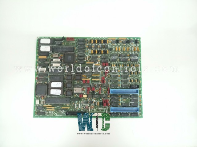
DS200TCCBG1ANE - Common Extended Analog I/O Board is available in stock which ships the same day.
DS200TCCBG1ANE - Common Extended Analog I/O Board comes in UNUSED as well as REBUILT condition.
To avail our best deals for DS200TCCBG1ANE - Common Extended Analog I/O Board, contact us and we will get back to you within 24 hours.
SPECIFICATIONS:
Part Number: DS200TCCBG1ANE
Manufacturer: General Electric
Series: Mark V LM
Product Type: Common Extended Analog I/O Board
Number of channels: 24
Input Signals: 4-20 mA
Power supply voltage: 28 V dc
Voltage Range: 14 to 32 V dc
Mounting: DIN-rail mounting
Technology: Surface mount
Operating temperature: -40°C to 85°C
Size: 30 cm high x 18 cm
Repair: 3-7 Day
Availability: In Stock
Country of Origin: United States
FUNCTIONAL DESCRIPTION:
DS200TCCBG1ANE is a Common Extended Analog I/O Board manufactured and designed by General Electric as part of the Mark V LM Series used in GE Speedtronic Gas Turbine Control Systems. The Common Extended Analog I/O Board (TCCB) handles scaling and conditioning for additional analog I/O signals from the TBCB terminal board on the
TCCB CONNECTORS:
2PL - Distributes power from the TCPS board in the
3PL - The Data Bus between the STCA, TCCA, and TCCB boards in core
JHH - Carries the 4.20 mA/0.1 mA input signals from the TBCB terminal board.
JII - Carries the RTD input signals from the TBCB terminal board.
JMP - Carries the potential and current transformer (PT and CT) signals from the TCEB board in the
TCCB RTD CIRCUIT:
The circuitry that supplies excitation to the RTDs from the TBCB terminal board is located on the TCCB board. A steady current is sent through the RTD and when the temperature changes, the resistance changes causing the voltage on the RTD to change. The TCCB board measures, scales, and conditions the voltages. The RTD signals are read from the TBCB terminal board by the TCCB board over the JCC and JDD connectors. The TCCB board sends the signals to the I/O Engine via the 3PL connector. The type of RTD is selected using I/O configuration constants.
TCCB CONFIGURATION:
HARDWARE: The hardware jumpers J1, J2, J3, J4, and J5 enable generator and bus voltage monitoring as well as line current monitoring in the Mark V LM. Jumper J14 connects the RS232 serial port to DCOM, while jumpers J15 and J16 are designated for testing purposes.
SOFTWARE: I/O configuration constants for RTDs, mA inputs, generator, and bus voltage, and line current settings are entered in the I/O Configuration Editor on the HMI as outlined below.
TCCB GENERATOR/BUS VOLTAGE AND CURRENT INPUT CIRCUITS:
Voltage signals from the generator and bus, along with current signals from the line (PT and CT), are scaled and conditioned on the TCCB board. The TCCB uses these signals to determine phase currents and voltages and calculate generator megawatts, power factor, and VARs for power system monitoring. These signals are received from the PTBA terminal board, scaled on the TCEB board in the
WOC has the largest stock of GE Speedtronic Control System Replacement Parts. We can also supply unused and rebuilt backed-up with a warranty. Our team of experts is available round the clock to support your OEM needs. Our team of experts at WOC is happy to assist you with any of your automation requirements. For pricing and availability on any parts and repairs, kindly contact our team by phone or email.
What is the primary function of the TCCB board?
The TCCB board is responsible for scaling and conditioning additional analog I/O signals, including 4-20 mA/0-1 mA inputs, RTDs, generator and bus voltage inputs, and line current inputs.
What hardware jumpers are associated with the TCCB board?
Jumpers J1, J2, J3, J4, and J5 provide generator and bus voltage monitoring as well as line current monitoring. Jumper J14 connects the RS232 serial port to DCOM, while J15 and J16 are used for testing.
What signals does the TCCB use to calculate generator parameters?
The TCCB uses scaled voltage signals from the generator and bus, and current signals from the line (PT and CT), to determine phase currents and voltages, as well as calculate generator megawatts, power factor, and VARs for power system monitoring.