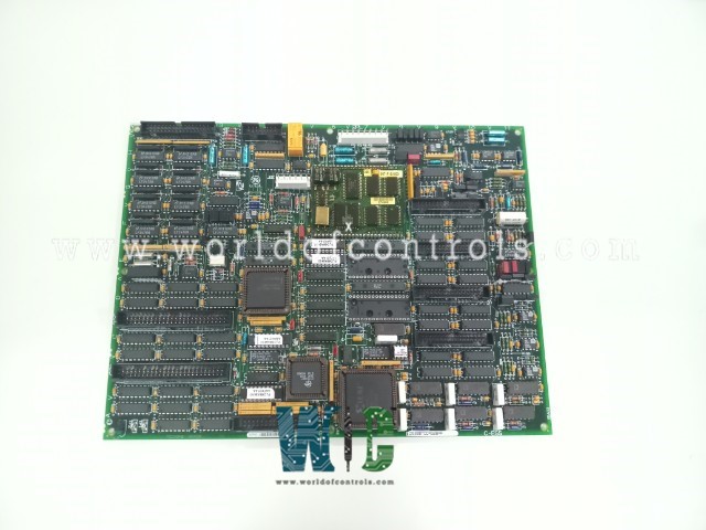
World Of Controls understands the criticality of your requirement and works towards reducing the lead time as much as possible.
DS200TCCAG2B - Common Analog I/O Board is available in stock which ships the same day.
DS200TCCAG2B - Common Analog I/O Board comes in UNUSED as well as REBUILT condition.
To avail our best deals for DS200TCCAG2B - Common Analog I/O Board, contact us and we will get back to you within 24 hours.
SPECIFICATIONS:
Part Number: DS200TCCAG2B
Manufacturer: General Electric
Series: Mark V
Location in System: R5 Core
Key Connectors: 2PL, 3PL
Hardware Jumpers J1: RS232 serial port
Product Type: Common Analog I/O Board
Signal Types: 4-20 mA
Signal Types Supported: 4-20 mA Input/Output
Country/Region of Manufacture: United States
Availability: In Stock
Manual: GEH-6153
FUNCTIONAL DESCRIPTION:
DS200TCCAG2B is a Common Analog I/O Board manufactured by General Electric as part of the Mark V Series used in gas turbine control management systems. The Common Analog I/O Board (TCCA), which is situated there, receives analog signals from the CTBA, TBQA, and TBCA terminal boards installed in the R5 core. Some of the signals in this group are 420 mA inputs and outputs, RTD inputs, thermocouple inputs, shaft voltage inputs, and shaft current inputs. The signals are written to the STCA board through the 3PL connector.
TCCA CONNECTORS:
CONFIGURATION:
TCCA 4 - 20 mA Input Circuit:
The TCCA board provides the circuitry for the 420 mA input signals. The signals from the CTBA terminal board are read using the JBB connector. The TCCA board measures the voltage drop across the burden resistor caused by the transducer current and writes the results to the I/O Engine through the 3PL connector.
TCCA 4-20 mA Output Circuit:
The TCCA board's circuitry sends 420 mA outputs through the JAA connector to the CTBA terminal board. These transmissions are typically used to power distant monitoring devices.
TCCA RTD CIRCUIT:
The circuitry for the TBCA terminal board, which stimulates the RTDs, is located on the TCCA board. A steady current is fed into the RTD, and when the temperature changes, the resistance shifts, changing the voltage on the RTD. The TCCA board calibrates, measures, and scales the voltage signal. The TCCA board reads the RTD signals from the TBCA terminal board via the JCC and JDD connectors. The signals from the TCCA board are sent to the I/O Engine using the 3PL connector. Constants in the I/O configuration are used to choose the RTD type.
THERMOCOUPLE CIRCUIT:
The thermocouple inputs are read by the TBQA terminal board. The TBQA terminal board's cold junction circuitry generates the cold junction signals. These variables are used by the TCCA board to calculate the cold junction correction. The TCCA board uses the thermocouple input and compensation value to calculate the actual temperature that the thermocouple reads. The I/O Engine reads the value through the 3PL connector. The types and curves of thermocouples are chosen based on the I/O configuration constants.
SHAFT MONITORING:
The TCCA board controls the voltage and current monitoring for the turbine shaft. Signals are read from the CTBA terminal board through the JBB connector and written to the I/O Engine using the 3PL connection. The R5 core location 2 houses the TCCA board. The Turbine Control R5> Micro Application Board A is what it is called. The following operations are defined by the TCCA configuration:
WOC has the largest stock of OEM Replacement Parts for GE Speedtronic Control Systems. We can also repair your faulty boards and supply unused and rebuilt boards backed up with a warranty. Our team of experts is available round the clock to support your OEM needs. Our team of experts at WOC is happy to assist you with any of your automation requirements. For pricing and availability on parts and repairs, kindly contact our team by phone or email.
What is the Common Analog I/O Board?
The Common Analog I/O Board is a crucial component in turbine control systems, responsible for processing various analog signals such as 4-20 mA inputs/outputs, RTD and thermocouple inputs, and shaft voltage/current signals.
How does the board communicate with other components?
Communication between the Common Analog I/O Board and other components of the turbine control system is achieved through connectors that allow for data transfer and system integration. These connectors link the board to other parts of the system, such as the I/O engine and other terminal boards, ensuring seamless data exchange.
What is the purpose of the jumpers on the board?
The Common Analog I/O Board features several jumpers that serve different purposes for system configuration and testing. Jumper 1 (J1) controls the activation of the RS232 serial port, allowing it to be turned on or off as needed.
WORLD OF CONTROLS warrants that from the date of delivery for a period of 36 months all UNUSED / REBUILT goods shall conform in all material respects with their description and any applicable specification.
WORLD OF CONTROLS warrants that from the point of delivery all Repairs will accord with their description and/or remain functional subject to the performance of the Repair Item for a period of 24 months.