World Of Controls understands the criticality of your requirement and works towards reducing the lead time as much as possible.
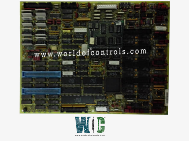
DS200TCCAG1ACA - Common Analog I/O Board is available in stock which ships the same day.
DS200TCCAG1ACA - Common Analog I/O Board comes in UNUSED as well as REBUILT condition.
To avail our best deals for DS200TCCAG1ACA - Common Analog I/O Board, contact us and we will get back to you within 24 hours.
SPECIFICATIONS:
Part Number: DS200TCCAG1ACA
Manufacturer: General Electric
Series: Mark V
Product Type: Terminal Board
Input Channels: 8 Analog Inputs
Input Resolution: 12-bit / 16-bit
Output Type: Voltage (0-10V, ±10V)
Output Resolution: 12-bit / 16-bit
Input Type: Voltage (0-10V, ±10V)
Communication Protocol: RS-485
Power Supply: 24V DC ±10%, < 5W
Isolation: 1500V
Mounting Options: DIN Rail
Operating Temperature: -20°C to 70°C
Country/Region of Manufacture: United States
Availability: In Stock
FUNCTIONAL DESCRIPTION:
DS200TCCAG1ACA is a Common Analog I/O Board manufactured and Designed by General Electric as part of the Mark V Series used in gas turbine control systems. The Common Analog I/O Board (TCCA), located in the
TCCA CONNECTORS:
TCCA CONFIGURATION:
Hardware: There are three hardware jumpers - J1, JP2, and JP3 on the TCCA board. J1 is used to enable/disable the serial RS232 port. JP2 is used to disable the oscillator for the card test. JP3 is used for factory tests. Refer to Appendix A for information on the hardware jumper settings for this board.
Software: I/O configuration constants for the thermocouples, RTDs, mA inputs and outputs, and the shaft voltage and current settings are entered in the I/O Configuration Editor located on the HMI as described below.
TCCA 4 - 20 mA INPUT CIRCUIT:
The TCCA board provides the circuitry for the 4-20 mA input signals. The signals are read from the CTBA terminal board via the JBB connector. The transducer current is dropped across a burden resistor and the voltage drop is read by the TCCA board and written to the I/O Engine via the 3PL connector.
TCCA 4 - 20 mA INPUT CIRCUIT:
The TCCA board provides the circuitry for driving 4-20 mA outputs to the CTBA terminal board via the JAA connector. These signals are typically used to drive remote instrumentation for monitoring.
SHAFT MONITORING:
The TCCA board manages the voltage and current monitoring for the turbine shaft. Through the JBB connector, these signals are read from the CTBA terminal board. The 3PL connector is used to write the signals to the I/O Engine. The R5 core location 2 houses the TCCA board. The Turbine Control R5> Micro Application Board A is what it is called. The following operations are defined by the TCCA configuration:
WOC has the largest stock of GE Speedtronic Control System Replacement Parts. We can also supply unused and rebuilt backed-up with a warranty. Our team of experts is available round the clock to support your OEM needs. Our team of experts at WOC is happy to assist you with any of your automation requirements. For pricing and availability on any parts and repairs, kindly contact our team by phone or email.
What is the function of a Common Analog I/O Board?
A Common Analog I/O Board serves as an interface between analog signals from sensors or devices and digital systems like controllers or computers. It enables the system to read analog inputs (such as voltage or current from sensors) and output analog signals (like controlling actuators). These boards are essential for applications in industrial automation, process control, and data acquisition.
What types of signals can the board handle?
The board is designed to handle both voltage and current signals. Typically, it supports voltage ranges like 0-10V, ±10V, and current signals such as 4-20 mA. This versatility makes it compatible with a wide variety of industrial sensors and actuators.
How many input and output channels does the board have?
The number of channels varies depending on the model. For example, a standard board might have 8 analog input channels and 4 analog output channels. These channels can operate independently and often include configurable settings to accommodate different signal types.