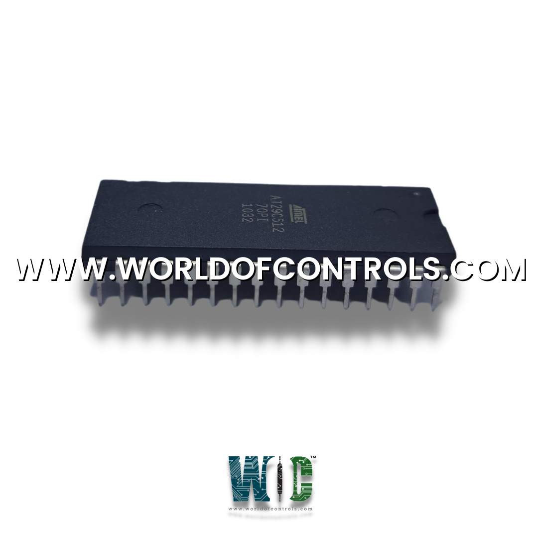
World Of Controls understands the criticality of your requirement and works towards reducing the lead time as much as possible.
DS200STCAP1AAB - Turbine Communication Board is available in stock which ships the same day.
DS200STCAP1AAB - Turbine Communication Board comes in UNUSED as well as REBUILT condition.
To avail our best deals for DS200STCAP1AAB - Turbine Communication Board, contact us and we will get back to you within 24 hours.
SPECIFICATIONS:
Part Number: DS200STCAP1AAB
Manufacturer: General Electric
Series: Mark V LM
Product Type: Turbine Communication Board
Number of relay channels: 12
Power supply voltage: 24 V dc
Power Requirements: +5 V dc, 6 A
Repair: 3-7 Day
Mounting: DIN-rail mounting
Technology: Surface mount
Operating temperature: -30 to +65°C
Size: 15.9 cm high x 17.8 cm
Availability: In Stock
Country of Origin: United States
Manual: GEH-6183
FUNCTIONAL DESCRIPTION:
DS200STCAP1AAB is a Turbine Communication Board manufactured and designed by General Electric as part of the Mark V LM Series used in GE Speedtronic Control Systems. The Turbine Communication Board (STCA) functions as the IONET master for the I/O cores. Each of the I/O cores has an STCA board. Signals are read through the various connectors, conditioned, and written to the I/O Engine located on the UCPB daughterboard via the bus connectors J1 and J3. The signals are written to the COREBUS connections located on the QTBA or CTBA boards via the JEE connector.
STCA CONFIGURATION:
Hardware: Hardware jumper JP2 enables the test points for factory testing. Hardware jumper JP4 selects the voltage needed for the flash EPROM. Refer to Appendix A and the hardware jumper screen on the operator interface for information on the hardware jumper settings for this board.
Software: I/O configuration constants for the pulse rate inputs, compressor stall detector, and synchronization settings are entered in the I/O Configuration Editor on the operator interface as described below.
STCA PULSE RATE INPUT CIRCUIT:
The STCA board scales and conditions the pulse rate inputs read from the TCQC board. These signals originate from magnetic pickup devices whose signals are written to the TCQC board by the QTBA, TBQB, and/or PTBA terminal boards. The
STCA SYNCH CHECK CIRCUIT:
The generator and bus voltage inputs are read from the TCQC board via the 19PL connector. These signals originate on the PTBA terminal board in the
WOC has the largest stock of GE Speedtronic Control System Replacement Parts. We can also supply unused and rebuilt backed-up with a warranty. Our team of experts is available round the clock to support your OEM needs. Our team of experts at WOC is happy to assist you with any of your automation requirements. For pricing and availability on any parts and repairs, kindly get in touch with our team by phone or email.
What is the role of the Turbine Communication Board in a turbine control system?
The primary role of the Turbine Communication Board is to ensure smooth and reliable data exchange between different elements of the turbine control system. It helps in transmitting sensor data to the controller, receiving control commands from the controller, and providing feedback signals for monitoring and diagnostics.
What types of communication protocols are supported by Turbine Communication Boards?
Turbine Communication Boards typically support various communication protocols such as Modbus, Profibus, Ethernet/IP, DeviceNet, and CANbus, among others. The choice of protocol depends on the specific requirements of the turbine control system and the compatibility of the devices involved.
How does the Turbine Communication Board ensure data integrity and reliability?
Turbine Communication Boards employ error-checking mechanisms such as checksums, cyclic redundancy checks (CRC), and packet acknowledgment to ensure data integrity during transmission. Additionally, they may implement protocols for retransmission of lost or corrupted data packets to enhance reliability.