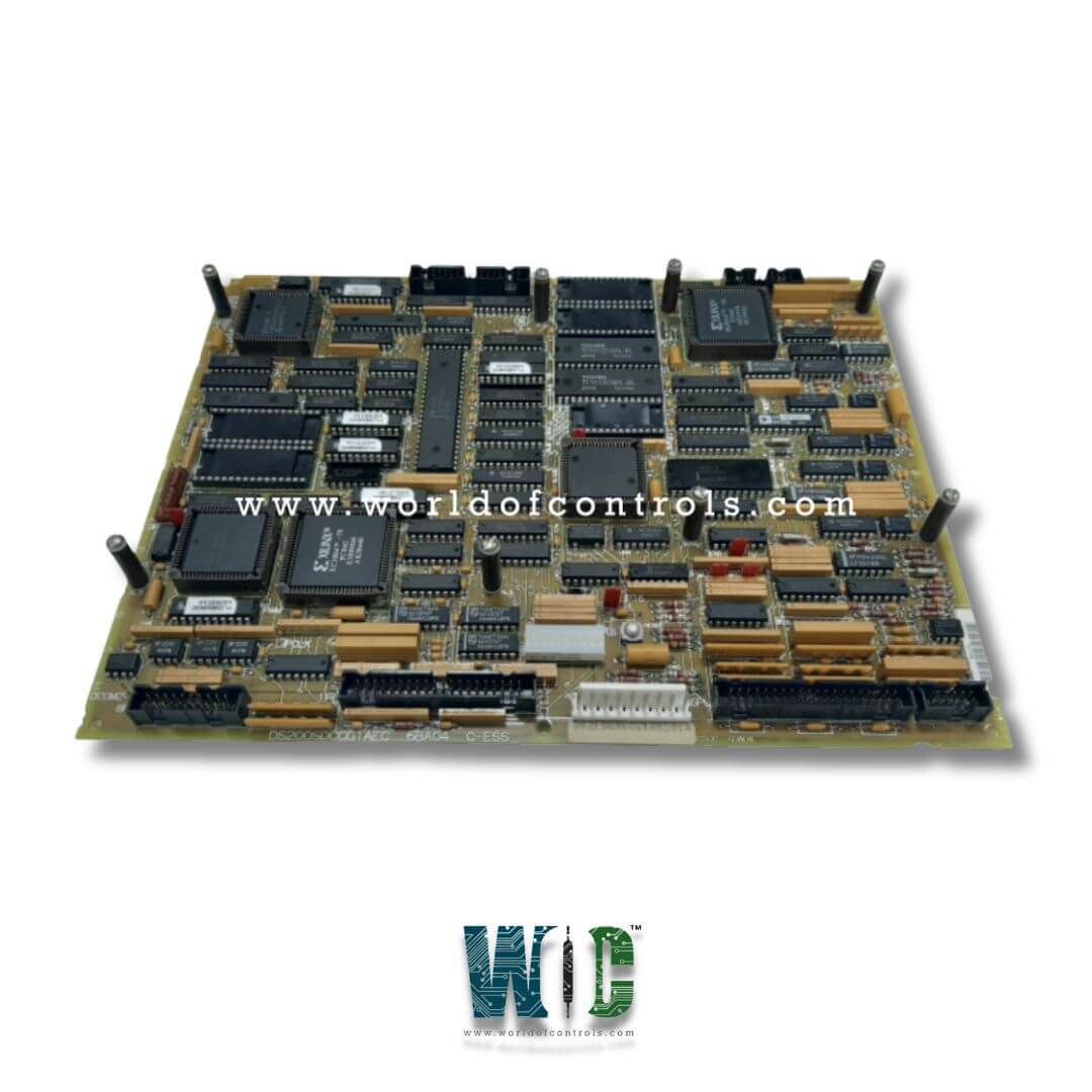
DS200SDCCG1AFD - Drive Control Card

DS200SDCCG1AFD - Drive Control Card DS200SDCCG1AFD - Drive Control Card

World Of Controls understands the criticality of your requirement and works towards reducing the lead time as much as possible.

DS200SDCCG1AFD - Drive Control Card is available in stock which ships the same day.

DS200SDCCG1AFD - Drive Control Card comes in UNUSED as well as REBUILT condition.

To avail our best deals for DS200SDCCG1AFD - Drive Control Card, contact us and we will get back to you within 24 hours.

SPECIFICATIONS:

Part No: DS200SDCCG1AFD
Manufacturer: General Electric
Function: Digital Signal Conditioning Card
Series: Mark V
Input Voltage: 24 VDC
Operating Temperature: 0°C to 70°C
Board Size: 6.25 in x 4.25 in (15.88 cm x 10.80 cm)
Availability: In Stock
Country of Origin: USA
Manual: GEI-100029

FUNCTIONAL DESCRIPTION:

DS200SDCCG1AFD is a Drive Control Card manufactured and designed by General Electric as part of the Mark V series used in GE Speedtronic Turbine Control Systems. The SDCC contains the primary control circuitry and software for a drive or exciter. The SDCC consists of three 16-bit microprocessors and associated circuits coupled via dual-ported RAM. (Dual-ported RAM [DPR] is RAM configured as memory arrays that can be independently and simultaneously accessed by two microprocessors.) The SDCC also includes interface circuitry that connects with other boards to form various types of AC and DC motor drives. The interface circuitry controls and processes drive and motor signals, and customer I/O. (The interface circuitry and three main microprocessors are used for other functions in TC2000 applications.) The SDCC's three main microprocessors are:

  • Drive Control Processor (DCP). An 80C186 microcontroller (U1) with numerous built-in peripheral functions and uses both digital and analog I/O.
  • These functions include address decoding for chip selects, wait-state generators, an interrupt controller, timer/counters, and the direct memory access (DMA) controller. DCP software consists of user interfaces, outer regulating loops (such as speed and position), and system-level functions.
  • Motor Control Processor (MCP). An 80C196 microcontroller (U21) with high-speed I/O, conventional digital I/O, analog I/O, timer/counters, and a watchdog timer. MCP software consists of inner loops such as current regulators, and motor/technology-specific functions such as dc phase control, ac motion control, and ac general purpose.
  • Co-motor Processor (CMP). A TMS320C25 digital signal processor (U35) that performs math-intensive functions for motor control algorithms is too complex for the MCP. The SDCC uses this processor and its associated circuitry only when the drive requires additional processing capability. The CMP interfaces only to its EPROM and MCP/CMP dual-ported RAM.
  • The DS200SDCC card includes onboard software stored in five memory chips: four EPROMs (U11, U12, U22, and U23) that contain configuration data programmed at the factory and one EEPROM (U9) that contains field-adjustable parameters. These memory chips are contained in sockets on the SDCC.

SDCC CARD CONNECTIONS:

Eight connectors (marked _PL) connect the SDCC to the other controller boards and external signals. The positions of the connections are depicted in Figure 3 along with tables 3 through 9 that list the pin signals for each connector. The following are connectors to other boards:

The Power Supply/Interface Board's 2PL inputs at 5, 15, and 24 V dc are connected to the SDCC. The LAN Communications Card receives outputs from the 3PL SDCC (DS215SLCC)

  • 6PL I/O between the SDCC and the Simple Drive Terminal Board (DS200STBA) or Drive Terminal Board (531X305NTB).
  • 7PL I/O between the SDCC and the Multibridge Signal Processing Card (DS200SPCB) or Signal Processor Card (531X309SPC) (not present on SDCCG3s)
  • 8PL I/O between the SDCC and the Simple Drive Terminal Board (DS200STBA) or Drive Terminal Board (531X305NTB).
  • 9PL - Not Used: (not present on SDCCG3s) SDCC outputs to 11PL meters (not present on SDCCG3s)

SOFTWARE CONFIGURATION TOOLS:

Any adjustment, downloading, or replacement of software on the SDCC requires the use of the ST2000, GE Control System Toolbox, or LynxOS Drive Configurator. The applicable drive/exciter instruction book, an appropriate PC, and the ST2000, GE Control System Toolbox, or LynxOS Drive Configurator instruction book are also required for any software adjustments.

  • ST2000 is a DOS-based set of software tools for configuring GE DIRECTO-MATIC 2000 control equipment.
  • The GE Control System Toolbox is a Windows-based set of software tools for configuring GE DIRECTO-MATIC 2000 control equipment.
  • The LynxOS Drive Configurator is a set of software tools for configuring GE DIRECTO-MATIC 2000 control equipment. It is designed to run on a personal computer (PC) operating with the LynxOS operating system.

WOC has the largest Stock of GE Speedtronic Turbine Control Systems OEM Replacement Parts. We can also repair your faulty boards and supply unused and rebuilt boards backed up with a warranty. Our team of experts is available round the clock to support your OEM needs. Our team of experts at WOC is happy to assist you with any of your automation requirements. For pricing and availability on any parts and repairs, kindly contact our team by phone or email.

FREQUENTLY ASKED QUESTIONS:

What is a Digital Signal Conditioning Card?

A Digital Signal Conditioning Card is a critical component used in various industrial control systems to process and condition signals received from sensors. By enhancing the accuracy and reliability of these signals, the card ensures that the data transmitted to the control system is of high quality. This conditioning involves filtering out noise, scaling the signals appropriately, and converting analog signals into digital formats that can be easily processed by control algorithms.

What types of signals can be conditioned?

Digital Signal Conditioning Cards are versatile and can handle a variety of signal types. They are designed to condition analog voltage and current signals, as well as signals from thermocouples and Resistance Temperature Detectors (RTDs). This capability allows them to support different sensor outputs, making them suitable for a wide range of applications, from monitoring temperature and pressure to controlling machinery.

How does signal conditioning improve sensor data?

Signal conditioning improves the quality of sensor data through several processes. By filtering electrical noise, the card ensures that only the relevant signals are passed through, which is essential for accurate readings. Additionally, scaling adjusts the signals to fit the operational ranges required by the control system. The card may also convert analog signals into digital formats, allowing for easier manipulation and processing by the control unit, ultimately leading to more precise control of industrial processes.