SPECIFICATIONS
Part No.: DS200RTBAG5A
Manufacturer: General Electrics
Country of Manufacture: United States (USA)
Product Type: Relay Terminal Card
Dimensions: 45 × 35 × 32 cm
Availability: In Stock
Series: EX2000
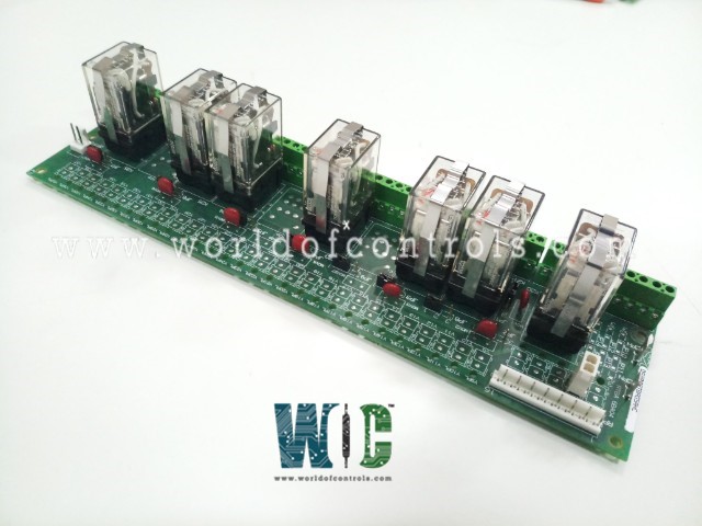
DS200RTBAG5A is a relay terminal board developed by General Electrics. It is used in the GE Excitation EX2000 digital Exciter system and Drive Control Cabinet. The board can be found within the drive (or exciter) cabinet as an optional card. The RTBA board contains ten relays that can be controlled directly from the pilot relays on the LTB LAN I/O Terminal Board (LTB) or remotely by the user. Seven of the ten relays (DPDT relays) have two Form C contacts, while the remaining three relays have four Form C contacts (4PDT relays).
DS200RTBAG5A Relay Description
- The ten relays are denoted by the letters K20 through K29. Relays K20 K26 are DPDT relays, while K27 K29 are 4PDT relays (see Figure 1). Each relay has an LED (located at the top of the relay inside the relay's case) that indicates when the relay is energized.
- All relay I/O is protected by 130 V ac metal oxide varistors (MOVs). If necessary, any of the ten relays can be replaced individually. The part numbers of the relays per RTBA board group number are listed in Table 1.
Relay Replacement
- Turn off the drive's power.
- Open the cabinet door on the drive to gain access to the board. (The RTBA board is usually found beneath the drive's board rack.)
- To replace the relay, remove the retaining clip by pressing on the top of the clip and pulling on either side of the clip to release it.
- Pull the old relay straight out of the relay socket.
- Place the new relay in the socket (it will only fit one way) and press it into place.
- Center the new relay's retaining clip over the relay and press on the top until the bottom of the clip engages on the relay socket.
DS200RTBAG5A Board Connections
- The RTBA board is connected to the LTBA board via a 16-pin connector (RPL) and a 2-pin connector (OPTPL).
- The usage of certain signals of the RPL connector is jumper selectable. Table 2 contains descriptions of RTBA board jumpers. To supply control power to certain pluggable circuits, two stab connectors, CPH (control power hot, positive) and CPN (control power negative), are provided. The usage of these stab connectors is jumper selectable.
- The RTBA board includes pluggable circuits as well as access to relays K27 and K29 via connectors C1PL C5PL and Y9PL Y37PL.
- The control power source for these pluggable circuits can be selected via a jumper. The descriptions of the C1PL C5PL and Y9PL Y37PL connectors can be found in Table 6. I/O between the RTBA board relays K20 − K26 and external signals can be connected at RTBA board terminals 1 − 52.
Configurable Hardware
Berg-type (manually movable) hardware jumpers on the RTBA board are identified by a JP nomenclature and must be set correctly for the application. The majority of the jumper options have been pre-programmed.
Board Replacement Procedure
- Turn off the drive and wait several minutes for all of the capacitors to discharge. Before touching any electrical circuits, make sure the power is turned off.
- To access the board, open the cabinet door on the drive. (The RTBA board is usually found beneath the drive's board rack.)
- Disconnect all cables from the RTBA board with care as follows:
- For ribbon cables, gently pull the cable connector loose by grasping each side of the cable connector that mates with the board connector.
- Pull the pull tab carefully on cables with pull tabs.
- Loosen the screw at the top of each terminal and carefully pull each wire-free for wires attached to RTB terminals. (Be sure to label the wires to make reconnection easier.)
- Integral holding clips are available on two-conductor plugs (CP1PLCP5PL and Y9PLY37PL). To disconnect the connector, press the connector lever.
- Remove the four screws with washers that secure the RTBA board to the four standoffs.
- Place all configurable items on the replacement (new) board in the same position as those on the replaced board (old board).
- Place the new board on the four standoffs using the four screws and washers that were removed in step 4.
- Reconnect all cables that were disconnected in step 3, making sure that each connector is properly seated at both ends.
- Reconnect all individual wires disconnected in step 3 (as labeled), making sure that each wire is securely fastened in the terminal.
The most extensive assortment of GE Excitation control replacement components can be found at World of Controls. Our experts are here to assist you with your requirements at any time. Please contact WOC if you require any additional information.
FREQUENTLY ASKED QUESTIONS
What is DS200RTBAG5A?
DS200RTBAG5A is a relay terminal board and it is used in the GE Excitation EX2000 digital Exciter system and Drive Control Cabinet.
How do I Set up the Relay Power Source?
The power supply for the relays on the board is defined by jumpers.
What is the Use of a Relay Card?
To connect a control system low-level control output to higher-level loads like a low-voltage screen controller.
