SPECIFICATIONS
Part No.: DS200NATOG2ABB
Manufacturer: General Electric
Country of Manufacture: United States of America (USA)
Product Type: Voltage Feedback Scaling board
Availability: In Stock
Series: LCI
Functional Description
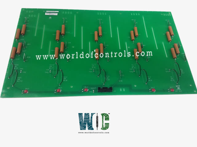
DS200NATOG2ABB is a Voltage Feedback Scaling board developed by GE. It is a part of the LCI series. The board is specifically designed to attenuate both AC and DC voltages, ensuring that the voltage feedbacks derived from the SCR bridge are accurate and reliable. This precision is essential for maintaining the optimal performance and reliability of power control systems.
Features
- The primary function of the board is to attenuate the high AC and DC voltages present in the SCR bridge to manageable levels. By doing so, it allows for precise voltage feedback, which is critical for the accurate monitoring and control of the power system. This attenuation ensures that the feedback data used for controlling the SCR bridge is accurate, leading to better regulation and stability of the power system.
- The board does not work in isolation; it operates in conjunction with two other key components: the VME backplane and the gate distribution and status board. The VME backplane is a versatile bus system that provides the necessary interconnections and communication pathways between various boards and modules within a system. This ensures that the NATO board can effectively communicate and exchange data with other system components.
- Additionally, the gate distribution and status board plays a significant role in this setup. It is responsible for distributing gate signals and providing status information within the power control system. By working closely with the NATO board, ensures that the attenuated voltage feedbacks are utilized correctly to control the gates of the SCRs, thereby managing the overall power distribution and regulation.
- The voltage feedback scaling board is a critical component in power control systems, providing accurate attenuation of AC and DC voltages in an SCR bridge. Its integration with the VME backplane and the gate distribution and status board ensures precise voltage feedback and efficient power regulation, contributing to the system's overall performance and reliability.
Input Configuration
- Precision Resistor Strings: The board contains five identical, series-connected strings of precision resistors. These strings are meticulously designed to ensure accurate voltage attenuation. The setup includes one string for each of the three AC phases and two additional strings for the positive and negative DC bus voltages. This configuration allows the board to manage multiple voltage sources simultaneously, ensuring comprehensive voltage feedback for the entire system.
- Input Stab Connectors and Wire Jumpers: To accommodate different voltage levels, each resistor string can be configured using a selection of three different input stab connectors and two wire jumpers. These components are crucial for setting the appropriate attenuation level for the input voltages. The flexibility provided by these connectors and jumpers allows the board to handle a range of input voltages effectively.
- Voltage Attenuation Levels: The board can be configured to attenuate various input voltages, specifically 6900 V, 4200 V, 3300 V, 2200 V, or 1200 V. This range of attenuation levels ensures that the board can be used in diverse applications, catering to different voltage requirements. The ability to handle such a wide range of voltages makes the NATO board a versatile and essential component in power control systems.
Output Configuration
- Output Connections: The outputs of the five series-connected resistor strings, which correspond to the three AC phases and the positive and negative DC bus voltages, are routed to a single 20-pin ribbon header. This centralized connection simplifies the integration of the NATO board with other system components, facilitating efficient data transmission and system configuration.
- Protective Mechanisms: To safeguard the output voltages, the board incorporates metal oxide varistors (MOVs). These MOVs play a critical role in protecting the board by preventing the output voltage of each resistor string from becoming excessively high. This protection is particularly important if the output ribbon circuit is interrupted while the input voltage is still present. Without this protection, excessive voltages could potentially damage the board or connected equipment, compromising system reliability and safety.
- Burden Resistor Location: An important aspect of the board’s design is the location of the burden resistor. Instead of being placed on the NATO board itself, the burden resistor is located on the gate distribution and status board. This strategic placement helps in managing the load and ensures that the voltage feedback is processed accurately. The burden resistor’s function is to convert the attenuated voltage feedback into a proportional current, which can then be used for monitoring and control purposes.
The WOC team is always available to help you with your LCI requirements. For more information, please contact WOC.
Frequently Asked Questions
What is DS200NATOG2ABB?
It is a voltage feedback scaling board developed by GE under the LCI series.
How do the different configurations (G1 and G2) affect the attenuation strings?
The different configurations of the G1 and G2 board groups permit combinations of stab connectors and group numbers to obtain one, two, three, four, five, or six resistors per attenuator string. This flexibility allows the board to be tailored to specific voltage attenuation requirements.
Why are wire jumpers used in the G2 board group?
Wire jumpers are used in the G2 board group to replace the two bottom resistors in each string. This reduces the total number of resistors to four per string, allowing for lower attenuation levels and enabling the board to handle lower input voltages effectively.
What are stab connectors and how are they used in the board?
Stab connectors are used to configure the input connections on the board. By selecting different stab connectors and combining them with the appropriate board group (G1 or G2), users can achieve the desired number of resistors per attenuator string to match the input voltage requirements.
