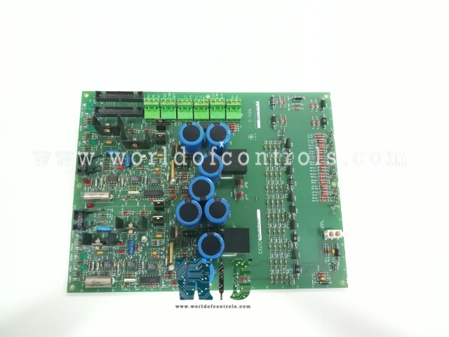
World Of Controls understands the criticality of your requirement and works towards reducing the lead time as much as possible.
DS200EXDEG1A - De-Excitation Control Board is available in stock which ships the same day.
DS200EXDEG1A - De-Excitation Control Board comes in UNUSED as well as REBUILT condition.
To avail our best deals for DS200EXDEG1A - De-Excitation Control Board, contact us and we will get back to you within 24 hours.
SPECIFICATIONS:
Part No: DS200EXDEG1A
Manufacturer: General Electric
Product Type: De-Excitation Control Board
Series: EX200
Exciter Connector Type: 34
Terminal Block: 12
Power Supplies: 240 Vdc
Operating Temperature: 0�C to 65�C
Availability: In Stock
Weight: 2.00 lbs
Size: 9.2 x 6.5 inches
Country of Origin: USA
Manual: GEI-100195
FUNCTIONAL DESCRIPTION:
DS200EXDEG1A is a De-Excitation Control Board manufactured and designed by General Electric and is part of the EX200 Series used in GE Excitation Turbine Control systems. The De-Excitation Control Board (EXDE) is the main printed circuit board used on exciters and the CV2000 Cycloconverter in the De-Excitation Module. The module consists of the EXDE board, a Conduction Sensor board, a steel core to concentrate flux for the conduction sensors, a 53 mm or 77 mm SCR, and the sheet metal base for mounting these devices. The De- -Excitation Module removes energy from the generator via the field when a normal or emergency generator shutdown occurs. The module limits the voltage across the generator field when the field breaker or contactors are opened and limits the energy dissipated in the contactors. The EXDE board comprises a thyristor and gate control logic to fire either a 53 mm SCR or 77 mm SCR. The SCR is fired when either of two control inputs is true, or when the anode-to-cathode voltage of the SCR exceeds a break-over voltage. An EXDE board is required to fire each SCR, however each board can be configured so that multiple boards can fire parallel SCRs with a synchronized firing pulse.
Two separate control circuits are provided on the EXDE board, control circuit 1 and control circuit 2, with three terminal boards each for connections to these control circuits. (See Figure 3 and Tables 5 through 10.) The firing control signal (firing pulse) is generated by applying 24 V dc from 1TB-2 to 1TB-1 for control circuit 1 and from 4TB-2 to 4TB-1 for control circuit 2. The output of a pulse transformer fires the SCR. Berg jumpers isolate the circuit 1 and circuit 2 pulse transformers from the SCR (see Table 1). Several large capacitors on the EXDE board hold up the dc voltage long enough to fire the SCR when power is removed.
CONDUCTION SENSOR AND INTERFACE:
The Conduction Sensor Board is also a component of the De-Excitation Module and provides the current flow sensing input to the EXDE board. The Conduction Sensor Board contains two Hall Effect sensors (per sensor circuit) that sense magnetic flux and output a digital signal. The sensors are mounted such that one can detect flux in one direction and the other detects flux in the opposite direction. The outputs of the sensors within each sensor circuit are diode-connected. Connector JCX supplies power (12 V dc) from the EXDE board to conduction sensor 1 and carries an input signal back to the control circuit 1 on the EXDE board (see Table 13). Connector JCY performs the same for conduction sensor 2 and control circuit 2 (see Table 14). A low output (near 0 V dc) indicates the presence of flux, and a high output (near 12 V dc) indicates the lack of flux.
SCR FIRING VOLTAGE:
Anode firing voltage for the SCR is selectable via wire jumpers that select the break-over diodes (BODs) and current-limiting resistors. There are five BODs in the series. BODs fire when a certain voltage level from anode to cathode is exceeded and once they turn on, they continue to conduct. The wire jumper from E7A to E7B through E12 selects the BODs that are in series and thus the break-over voltage. The wire jumper from E1B to E2 through E6, or to E1C selects the current limiting resistors that determine the gate current based on the BOD�s break-over voltage. A current-limiting resistor must be used to limit the SCR gate current when the BODs break over. The anode of the SCR is connected to stab connector E1A. (See Figure 3 and Table 2 for wire jumpers.)
WOC maintains the largest inventory of Replacement parts for GE Excitation Turbine Control systems. Additionally, we offer warranty-backed unused and rebuilt boards as well as board repairs for your damaged ones. For your OEM needs, our team of professionals is available around the clock. We at WOC are happy to help you with any needs you may have in terms of automation. Please get in touch with our team by phone or email for pricing and availability on any components and repairs.
How does the De-Excitation Module function?
The De-Excitation Module uses the EXDE board to limit the voltage across the generator field and control the energy dissipation in contactors during shutdown scenarios.
What components are included in the De-Excitation Module?
The module comprises the EXDE board, a Conduction Sensor Board, a steel core for flux concentration, a 53 mm or 77 mm SCR, and a sheet metal base for mounting.
What is the role of the Conduction Sensor Board?
The Conduction Sensor Board provides current flow sensing inputs to the EXDE board using Hall Effect sensors, detecting magnetic flux and outputting digital signals based on flux presence or absence.