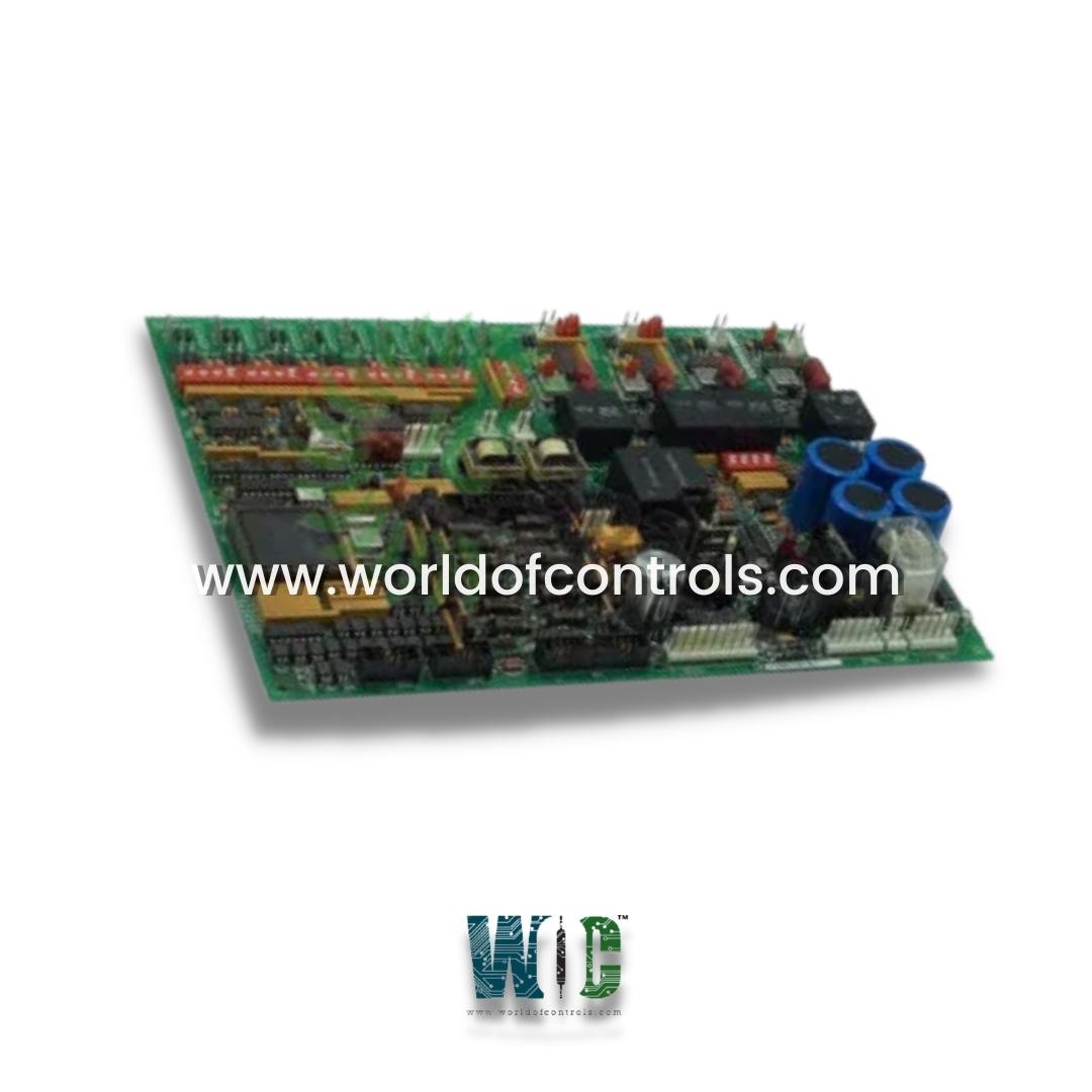
World Of Controls understands the criticality of your requirement and works towards reducing the lead time as much as possible.
DS200DCFBG2B - Power Supply Board is available in stock which ships the same day.
DS200DCFBG2B - Power Supply Board comes in UNUSED as well as REBUILT condition.
To avail our best deals for DS200DCFBG2B - Power Supply Board, contact us and we will get back to you within 24 hours.
Part Number: DS200DCFBG2B
Manufacturer: General Electric
Series: EX2000
Product Type: Power Supply Board
Number of input channels: 12
Number of outputs: 125 V dc
Trip Solenoid Rating: 125 V dc
Power supply voltage: 28 V dc
Voltage Range: 18 - 32 VDC
Mounting: DIN-rail mounting
Technology: Surface mount
Operating temperature: 40 to 70 degrees Celsius
Size: 33.0 cm high x 17.8 cm
Repair: 3-7 Day
Availability: In Stock
Country of Origin: United States (USA)
Manual: GEI-100028C
DS200DCFBG2B is a Power Supply Board manufactured and designed by General Electric. It is a part of EX2000 Series used in IGBT drive applications. The board is put to a different use by the EX2000 than it is by a drive. Italics in parentheses are used to indicate information that is different for the EX2000 applications. The Power Supply Board supplies control-level power to the drive and 115 V ac power (NA) to the enclosure fans by receiving 38 and 115 V ac (24 V dc) input power from the control power transformer (CPT). The following circuits are present on the board:
The Power Supply Board supplies control-level power to the drive and 115 V ac power (NA) to the enclosure fans by receiving 38 and 115 V ac (24 V dc) input power from the control power transformer (CPT). The following circuits are present on the board:
WOC has the largest stock of GE Drive Control System Replacement Parts. We can also repair your faulty boards. WOC is happy to assist you with any of your automation requirements. For pricing and availability on any parts and repairs, contact us with our team by phone or email.
What is DS200DCFBG2B?
It is a Power Supply Board manufactured and designed by General Electric.
What is the board used for?
It is used in IGBT drive applications for various products including DC2000, CB2000, EX2000, FC2000, GF2000, ME2000, and AC2000.
What is the purpose of the DCFB in the EX2000 application?
The board is used for a different purpose in the EX2000 application than in the IGBT drive applications.
What input power does the board receive?
It receives 38 and 115 V AC input power from the control power transformer (CPT). In some cases, it may receive 24 V DC input power instead.
What type of power does the card provide?
The card provides control-level power to the IGBT drive and 115 V AC power to the enclosure fans in some cases.
What is the purpose of DIP switch SW5?
DIP switch SW5 is used to scale the voltage applied to the circuit.
What is the purpose of the two other VCO circuits?
The two other VCO circuits provide feedback of the input voltage from a shunt. The VCO output frequency signals are sent to the SDCC/LDCC board through connector 1PL.