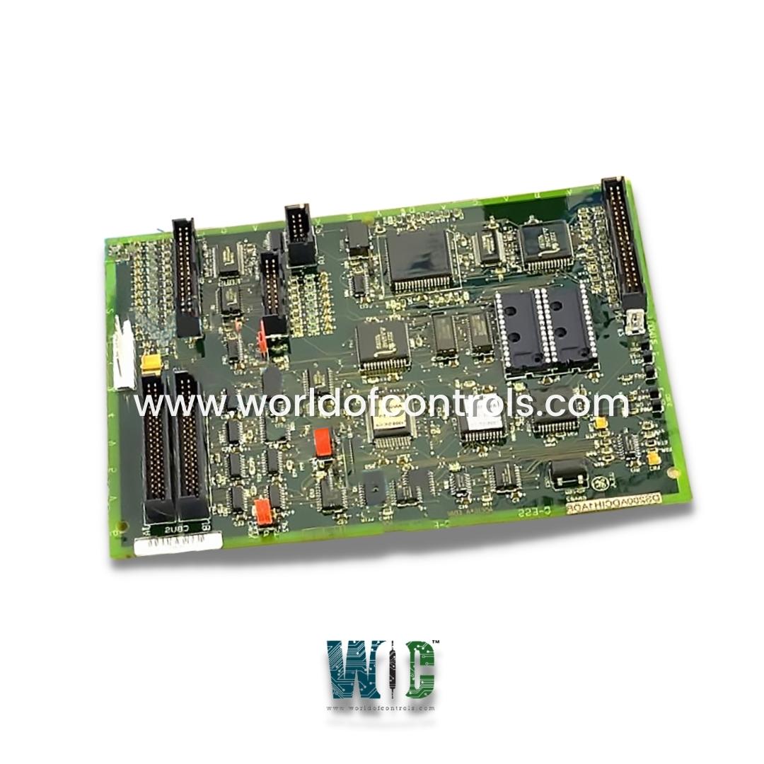
World Of Controls understands the criticality of your requirement and works towards reducing the lead time as much as possible.
DS200ADCIH1ADB - Analog-to-Digital Converter Interface Board is available in stock which ships the same day.
DS200ADCIH1ADB - Analog-to-Digital Converter Interface Board comes in UNUSED as well as REBUILT condition.
To avail our best deals for DS200ADCIH1ADB - Analog-to-Digital Converter Interface Board, contact us and we will get back to you within 24 hours.
SPECIFICATIONS:
Part Number: DS200ADCIH1ADB
Manufacturer: General Electric
Series: EX2000
Product Function: Analog-to-Digital Converter Interface Board
Power Requirements: +5 V dc, 6 A
Number of relay channels: 12
Trip Solenoid Rating: 125 V dc
Power supply voltage: 28 V dc
Voltage Range: 18 - 32 VDC
Mounting Option: DIN-rail mounting
Technology: Surface mount
Operating temperature: -30 to +65 degrees Celsius
Size: 15.9 cm high x 17.8 cm width
Product Type: PCB
Repair: 3-7 Day
Availability: In Stock
Country of Manufacturer: United States (USA)
Manual: GEH-5979
FUNCTIONAL DESCRIPTION:
DS200ADCIH1ADB is an Analog-to-Digital Converter Interface Board manufactured and designed by General Electric as part of the EX2100 Series used in GE Excitation Control Systems. The Analog-to-Digital Converter Interface (ADCI) Board is a component designed to facilitate the conversion of analog signals to digital signals in an electronic system. This board typically includes the necessary circuitry to interface with analog sensors or inputs, converting the continuous analog signals into discrete digital values that can be processed by digital systems. The ADCI Board commonly features connectors, jumpers, and integrated circuits to handle the conversion process. It plays a crucial role in systems where accurate and reliable digitization of analog data is essential, such as in industrial control systems, measurement devices, or any application where analog signals need to be processed digitally.The adapter card serves as a bridge between the turbine control system and a computer or device, enabling the exchange of data between the two systems. This card is equipped with diverse inputs and outputs for monitoring and regulating the turbine, encompassing features like temperature sensors, pressure sensors, and valve controls. The GE Genius Adapter Board features four jumpers, one 20-pin connector, and three 40-pin connectors. Additionally, it incorporates two programmable memory (PROM) modules. The 40-pin and 20-pin connectors of the ADCI (Analog-to-Digital Converter Interface) link to ribbon cables responsible for carrying control signals. These control signals are received by the board for processing, and certain signals are further transmitted to other boards and components within the drive system.
FEATURES:
Analog Signal Inputs: The board typically includes connectors or terminals to accept analog signals from external sources, such as sensors or devices that produce continuous voltage or current signals.
ADC Components: Integrated Analog-to-Digital Converters (ADCs) are a key component of the board. These convert the incoming analog signals into digital values, allowing for easier processing by digital systems.
Precision and Resolution: ADCI boards often emphasize precision and resolution, ensuring accurate conversion of analog signals into digital representations with minimal loss of information.
Connector Types: The board may feature specific connectors such as 40-pin or 20-pin connectors, allowing for standardized connections to other components or devices within a system.
Jumpers: Jumpers on the board provide a means to configure or customize certain aspects of the conversion process or signal handling, offering flexibility in adapting to different system requirements.
PROM Modules: Some ADCI boards include programmable memory (PROM) modules. These modules store configurations or settings related to the ADC operation, allowing for customization based on specific application needs.
Signal Processing Capabilities: The board may incorporate additional circuitry for signal processing, filtering, or conditioning to enhance the quality and reliability of the converted digital signals.
Interfacing with Control Signals: In systems where the ADCI board is part of a larger setup, it may have connectors or interfaces for control signals. These connections enable seamless integration with other boards or components within the system.
Transmission of Processed Signals: After converting analog signals to digital, the board may transmit these processed signals to other components or boards in the overall system, contributing to the system's functionality.
WOC has the largest stock of GE Excitation Control System Replacement Parts. We can also repair your faulty boards. WORLD OF CONTROLS can also supply unused and rebuilt backed-up with a warranty. Our team of experts is available round the clock to support your OEM needs. Our team of experts at WOC is happy to assist you with any of your automation requirements. For pricing and availability on any parts and repairs, kindly get in touch with our team by phone or email.
What is the purpose of an ADCI Board?
The ADCI Board is designed to convert analog signals, which are continuous electrical signals, into digital format, which consists of discrete values. This conversion is essential for interfacing analog sensors with digital systems.
How does an ADCI Board work?
The board uses integrated Analog-to-Digital Converters (ADCs) to sample and quantify incoming analog signals. These signals are then converted into digital values that can be processed and utilized by digital systems.
What types of analog signals can an ADCI Board handle?
ADCI Boards are versatile and can handle various types of analog signals, including voltage and current signals. They are commonly used in applications where precise conversion of analog data is crucial.