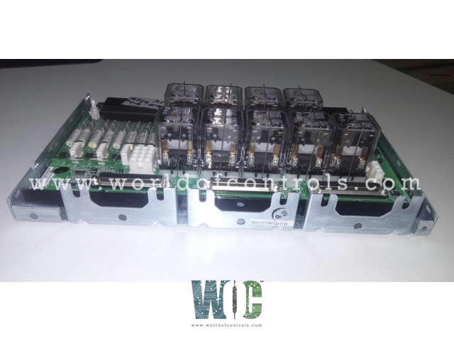
SPECIFICATIONS
Part No.: IS210TRPGH1BA
Manufacturer: General Electric
Country of Manufacture: United States of America (USA)
Trip solenoids 3 solenoids per TRPG
Solenoid rated voltage: 125 V dc
Solenoid rated current: 1 A
Product Type: Turbine Trip Output Board
Availability: In Stock
Series: Mark VIe
Functional Description
IS210TRPGH1BA is a turbine trip output board developed by GE. It is a part of Mark VIe control system. The terminal board is a critical component controlled by the I/O controller, serving as a pivotal interface for various operational functions within the system. Its integration with trip solenoids, collaboration with the TREG module, flame detection capabilities, and robust voting logic underscore its significance in ensuring the safety, reliability, and efficiency of system operations.
Features
- Relay Integration for Trip Solenoids: Boasts nine magnetic relays organized into three voting circuits, specifically designed to interface with trip solenoids, referred to as Electrical Trip Devices (ETD). These circuits play a crucial role in ensuring the reliable operation of the system's protective mechanisms.
- Collaboration with TREG: Working in tandem with the module, TRPG forms the primary and emergency sides of the interface to the ETDs. This collaboration enhances the redundancy and reliability of the system, providing robust protection against potential faults or malfunctions.
- Flame Detection Capabilities: In addition to its role in trip solenoid control, TRPG also accommodates inputs from eight Geiger Mueller flame detectors, primarily utilized in gas turbine applications. This functionality enhances the safety and efficiency of operations, particularly in environments where flame detection is essential.
- Primary Trip Functionality: The I/O board interfaces to provide the primary trip function, exerting control over the relays on the board. These relays, in turn, actuate the main protection solenoids, facilitating swift and effective response to critical events or abnormalities.
- Two-out-of-Three Voting Logic: In Triple Modular Redundancy (TMR) applications, the three inputs undergo hardware-based voting using a relay ladder logic two-out-of-three voting circuit. This robust logic ensures that the system remains operational even in the event of component failures or discrepancies.
- Monitoring and Diagnostics: The I/O board continuously monitors the current flow in its relay driver control line to ascertain the energize or de-energize vote/status of the relay coil contact status. Additionally, supply voltages are meticulously monitored for diagnostic purposes, enabling proactive identification and resolution of potential issues.
- Diagnostics for Relay Operation: To ensure proper functionality, a normally closed contact from each relay on the board is monitored by the diagnostics. This comprehensive monitoring approach enhances system reliability by promptly detecting and addressing any deviations from expected operation.
Product Attributes
- Trip solenoids: Each TRPG unit features three solenoids.
- Solenoid rated voltage/current: They operate at a standard 125 V DC with a maximum draw of 1 A, and alternatively at 24 V DC with the same draw (H1B, H2B, H3B).
- Solenoid response time: The L/R time constant is 0.1 seconds.
- Current suppression: There's a metal oxide varistor (MOV) installed on the TREG for electrical surge protection.
- Current economizer: Terminals are available for an optional 10-ohm, 70 W economizing resistor on the TREG to enhance energy efficiency.
- Control relay coil voltage supply: Relays receive a 28 V DC supply from JR1, JS1, and JT1.
- Flame detectors: Each TRPG unit is equipped with eight detectors.
- Flame detector supply voltage/current: They operate at 335 V DC with a current draw of 0.5 mA per detector.
Control Relay Coil Voltage Supply
- Voltage Supply Source: The control relay coils receive their operating voltage from the JR1, JS1, and JT1 connectors, where they are supplied with a stable 28 V dc power.
- Reliability and Stability: This 28 V dc supply ensures reliable and stable operation of the control relay coils, enabling them to respond swiftly and accurately to control signals from the I/O board.
- Compatibility with System Components: The 28 V dc voltage supply is carefully chosen to match the operational requirements of the relays, ensuring compatibility and optimal performance within the system architecture.
Flame Detector Supply
- Flame Detector Quantity: Each board accommodates up to eight flame detectors, providing comprehensive coverage for flame detection applications.
- Voltage and Current Specifications: Flame detectors are supplied with 335 V dc voltage and draw a current of 0.5 mA per detector during operation.
- Optimal Performance: The 335 V dc supply voltage, coupled with the specified current draw, ensures optimal performance of the flame detectors, allowing them to effectively detect and respond to potential flame occurrences in gas turbine applications.
- Safety Considerations: The voltage and current specifications are carefully chosen to balance the need for effective flame detection with safety considerations, ensuring reliable operation without posing undue risk to system components or personnel.
The WOC team is always available to help you with your Mark VIe requirements. For more information, please contact WOC.
Frequently Asked Questions
What is IS210TRPGH1BA?
It is a turbine trip output board developed by GE under the Mark VIe series.
What diagnostics does the I/O board run on the terminal board?
The I/O board conducts diagnostics on various aspects of the board, including feedback from the trip solenoid relay driver and contact, solenoid power bus, and flame detector excitation voltage.
What triggers a diagnostic alarm on the TRPG?
A diagnostic alarm is triggered if any of the monitored signals on the board go beyond specified limits, indicating an unhealthy condition or potential fault.
What role do connectors JR1, JS1, and JT1 play in the diagnostics?
Connectors JR1, JS1, and JT1 on the terminal board are equipped with their own identification (ID) devices. These devices are interrogated by the I/O board, and if a mismatch is detected between the expected and actual IDs, a hardware incompatibility fault is generated.
