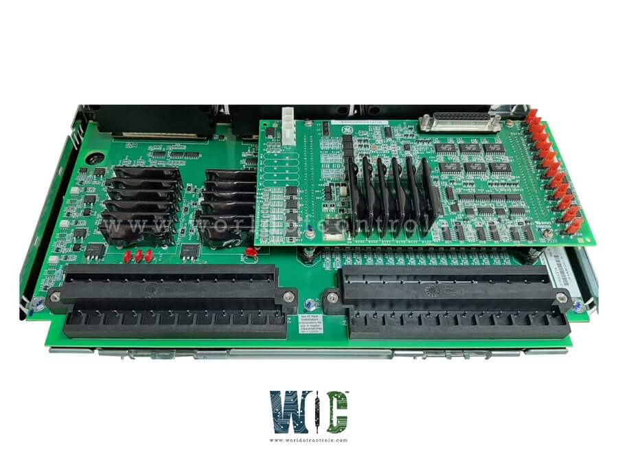
World Of Controls understands the criticality of your requirement and works towards reducing the lead time as much as possible.
IS210TREGH1B - Turbine Emergency Trip Terminal Board is available in stock which ships the same day.
IS210TREGH1B - Turbine Emergency Trip Terminal Board comes in UNUSED as well as REBUILT condition.
To avail our best deals for IS210TREGH1B - Turbine Emergency Trip Terminal Board, contact us and we will get back to you within 24 hours.
Part No.: IS210TREGH1B
Manufacturer: General Electric
Country of Manufacture: United States of America (USA)
Size: 33.0 cm high x 17.8 cm, wide
Technology: Surface mount
Temperature: -30 to 65oC
MPU pulse rate range: 2 Hz to 20 kHz
MPU pulse rate accuracy: 0.05 percent of reading
Number of inputs: 14
Number of outputs: 9
Contact ratings: NEMA class F.
Product Type: Turbine Emergency Trip Terminal Board
Availability: In Stock
Series: Mark VIe
IS210TREGH1B is a Turbine Emergency Trip Terminal Board developed by GE. It is a part of the Mark VIe control system. TREG supplies power to three emergency trip solenoids and is managed by the I/O controller. A maximum of three trip solenoids can be connected between the TREG and TRPG terminal boards. It delivers the positive side of the DC power to the solenoids, while TRPG provides the negative side.
Distributes DC power and maintaining control integrity across the emergency trip circuit. It ensures that the turbine can be safely and rapidly shut down when protection limits are exceeded.
The typical configuration includes:
Each of the three trip solenoids receives its power through dedicated relay channels, ensuring that any trip command issued by the Mark VIe controller is transmitted accurately and without delay. The design minimizes the risk of false trips while maintaining a fail-safe response in the event of a confirmed fault.
The TREG board incorporates a total of 12 relays, carefully structured to provide both control precision and redundancy. Out of these 12 relays, nine are organized into three groups of three, forming a three-channel voting logic system.
This configuration plays a crucial role in Triple Modular Redundancy (TMR) systems used in high-integrity turbine control environments. The three-channel voting arrangement ensures that:
The remaining three relays on the board perform auxiliary or monitoring functions, supporting trip verification and system diagnostics. This redundancy-based relay design ensures precise trip logic, which is essential for maintaining safe turbine operation and compliance with protection standards.
It serves as a central component in the emergency overspeed protection and emergency stop circuits of the turbine system. During critical fault conditions, the Mark VIe controller sends a trip signal to the TREG board, which in turn energizes or de-energizes the associated solenoids to isolate fuel supply and shut down the turbine safely.
Typical protective actions initiated through TREG include:
These functions ensure that the turbine system can transition to a safe shutdown state rapidly, preventing potential mechanical damage or safety risks.
The TREG board’s design emphasizes reliability, modularity, and fault tolerance, making it ideal for critical applications in gas, steam, and hydro turbine systems. Its robust construction ensures long-term performance even in demanding industrial environments characterized by high vibration, temperature variations, and electrical noise.
Key benefits include:
The board operates under the direct control of the I/O controller, making it a highly integrated and responsive component. Key connections include:
To ensure high reliability, operational safety, and system integrity, the I/O controller performs continuous and comprehensive diagnostics on the board and its connected components. These diagnostics play a crucial role in monitoring critical parameters, detecting anomalies, and preventing failures that could compromise turbine operations.
The diagnostic system monitors several essential aspects of the TREG board, including:
If any discrepancies, malfunctions, or abnormalities are detected during the diagnostic process, the system:
The WOC team is always available to help you with your Mark VIe requirements. For more information, please contact WOC.
What is IS210TREGH1B?
It is a Turbine Emergency Trip Terminal Board developed by GE under the Mark VIe series.
What is the role of the Turbine Emergency Trip Terminal Board in turbine protection?
It provides power to up to three emergency trip solenoids and is fully controlled by the I/O controller. It plays a crucial role in providing emergency overspeed protection and emergency stop functions. The system utilizes 12 relays on the TREG, nine of which are grouped in three sets of three-to-vote inputs, controlling the solenoids that are crucial for turbine safety.
What is the connection between TREG and TRPG boards?
TREG supplies the positive side of the DC power to the emergency trip solenoids, while the TRPG board provides the negative side of the power to complete the circuit. The I/O controller manages the communication and activation of trip functions between TREG and TRPG boards.
How does the TREG system work in simplex and redundant configurations?
In simplex systems, works with a third cable from J1 to the TSVO terminal board provides a servo valve clamp function when the turbine trips. The system can be configured with redundancy for enhanced reliability and fault tolerance.
What happens if there is a mismatch or fault in the system?
If the I/O controller detects a mismatch during diagnostics or identifies an incompatibility between the TREG board and other components (via the ID device), a hardware fault is triggered. This helps to ensure that only compatible and properly functioning hardware is used in the system, maintaining turbine safety.
How are the trip solenoids tested?
Trip solenoids can be tested using the application software in the controller, which allows the user to manually trigger each trip solenoid individually. Tests can be initiated through the PTR or ETR relays, confirming the solenoid circuit contacts, ensuring proper functionality of the emergency trip mechanisms.