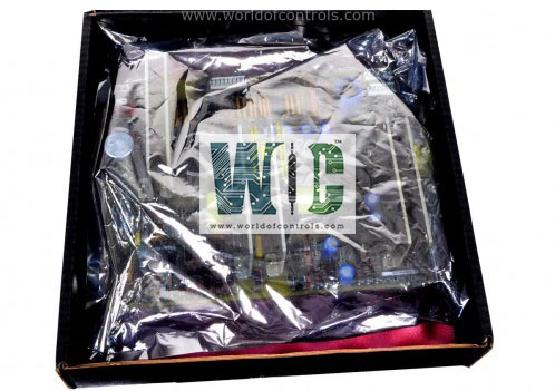
SPECIFICATIONS
Part No.: IS210TCSAH1A
Manufacturer: General Electric
Country of Manufacture: United States of America (USA)
Size: 10.16 cm wide x 33.02 cm high
Temperature: -30 to 65oC
Technology: Surface-mount
Product Type: Turbine Emergency Trip Board
Availability: In Stock
Series: Mark VIe
Functional Description
IS210TCSAH1A is a Turbine Emergency Trip Board developed by GE. It is a part of Mark VIe control system.The TCSA system utilizes the J2 connector to provide power, either 125 V dc or 24 V dc, to ETRs 1-3, located on TB5 SOL1 & SOL2, as well as TB6 SOL3. Similarly, the J3 connector supplies power to ETRs 4-9, situated on TB6 SOL4 - SOL9. This organized power distribution ensures proper functioning of the system components, facilitating seamless operation.
Normal Operating Conditions
- During regular operation, the mechanical force-guided relay, K6, is energized, concurrently activating the solid-state relays ETR1-3. This configuration allows for the smooth and efficient operation of the designated components, ensuring optimal performance under standard operating conditions.
- Similarly, the second mechanical force-guided relay, K7, is paired with ETRs 4-6, while the third relay, K8, is associated with ETRs 7-9, maintaining a systematic approach to relay control.
Trip Request Identification
- Any instance of de-energizing one or more ETR(s) is categorized as a trip request within the system.
- This comprehensive monitoring ensures that any deviation from the normal operating state is promptly identified and addressed, minimizing the risk of system malfunctions or disruptions.
- By categorizing ETR de-energization as a trip request, the system maintains a proactive stance towards maintaining operational integrity and safety.
Analog Input Accuracy
- The accuracy of the YSIL I/O pack analog inputs for the configured I/O pack is crucial for ensuring reliable data acquisition and system performance. This testing procedure aims to validate the accuracy of the analog inputs within specified limits.
- Test Setup
- Equipment Required: Obtain a multimeter and a signal source capable of generating current and voltages within the ranges of the configured YSIL I/O pack.
- Configuration Confirmation: Confirm the configured limits for 4-20 mA input types. This step ensures that the test values remain within the permissible range for accurate testing.
- Test Execution
- Selection of Test Values: Utilize the provided table of test values, selecting only those associated with the configured I/O point. Configuration changes are not required for this step.
- Application of Test Values: Apply the selected test values to the input channels of the configured I/O. Document the readings obtained from the YSIL for each test value, as observed in the Input tab within the ToolboxST application.
- Test Repetition: Repeat the testing procedure for each configured input channel, ensuring comprehensive coverage and accurate assessment of each analog input.
- Acceptance Criteria
- Accuracy Requirement: All measured values must fall within 2% of the full range input values for the input accuracy test to be considered acceptable. This criterion ensures that the analog inputs operate within specified tolerances, maintaining data integrity and system reliability.
- Out-of-Range Alert Verification: For any values that exceed the permissible range, confirm that the YSIL alerts the system through the Diagnostics tab and that the affected channel is flagged as unhealthy. This functionality ensures proactive identification of out-of-range inputs, facilitating timely corrective action and minimizing potential risks.
The WOC team is always available to help you with your Mark VIe requirements. For more information, please contact WOC.
Frequently Asked Questions
What is IS210TCSAH1A?
It is a Turbine Emergency Trip Board developed by GE under the Mark VIe series.
What items are tested and verified for each digital input using the ToolboxST application?
ContactInput(CFG) (Used/Unused) and SignalInvert(CFG) (Normal/Invert). The verification process ensures that the controllers can accurately receive the input data.
What is the test setup for verifying the digital input configuration?
Each configured digital input undergoes appropriate test cases to validate its configuration. The tests are conducted based on the specific configuration settings applied to each input.
What are the acceptance criteria for Test Case 1?
All three controllers must indicate True status when the inputs are jumpered. Inputs not jumpered should have a status of False. No voting diagnostics should be present, indicating agreement among the controllers regarding the input status.
