SPECIFICATIONS
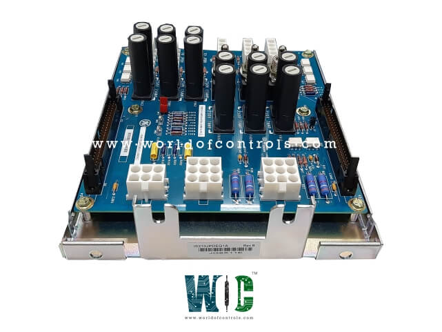
Part No.: IS210JPDEG1A Rev B
Manufacturer: General Electric
Country of Manufacture: United States of America (USA)
Number of channels: 8
Span: 0.3532 to 4.054 V
Maximum lead resistance: 15 ohm
Product Type: Battery Distribution Board
Availability: In Stock
Series: Mark VIe
Functional Description
IS210JPDEG1A Rev B is a Battery Distribution Board developed by GE. It is a part of Mark VIe control system. It is responsible for distributing DC power to terminal boards and other system loads, while also ensuring proper grounding and fault detection via feedback to the PPDA I/O pack. The board receives DC power from a battery or power supplies and distributes it to the terminal boards and other system components. It supports both 24V DC and 48V DC power, integrates with the PDM system, and helps detect ground faults through feedback provided by the PPDA.
Features
- DC Power Distribution: Receives DC power from a battery or power supplies and distributes it efficiently to other system loads and terminal boards. It supports a floating DC bus that is centered on earth using resistors. This unique design allows for accurate voltage feedback through the PPDA (Power Distribution Module) to detect potential system ground faults. The board can operate with either 24V DC or 48V DC, offering flexibility depending on system requirements.
- Feedback and Ground Fault Detection: The board integrates into the PDM (Power Distribution Module) system by providing feedback through the PPDA I/O pack. This allows the system to monitor the DC bus voltage and detect any ground faults. JPDE supports the detection of ground faults by using the voltage feedback to the PPDA, ensuring any discrepancies in the DC system are identified promptly.
- Power Supply Inputs: The board can support two power supplies, allowing it to be flexible in managing system power distribution. It provides inputs for these two power supplies, ensuring reliable power delivery to the terminal boards and other critical components. However, JPDE does not supply power to bulk 500W - 24V input / 28V output power supplies, which are responsible for providing I/O pack control power.
- Current Limitation: Due to the conventional construction of the board, there is a limitation on the current that can be passed through it. This means that the board is designed for managing lower-power applications and does not provide high current delivery for heavy-duty operations.
Installation
- Mounting Configuration: The board is base-mounted vertically on a metal bracket within the PDM cabinet. This helps secure the board in place while keeping it easily accessible for maintenance. The power input and output routing for the board are detailed in the wiring diagrams, ensuring proper connections to the power supplies and other components in the system.
- Diagnostic Connector: The board is equipped with a 50-pin diagnostic connector mounted at both the top and bottom of the board. This provides easy access for troubleshooting, diagnostics, and performance monitoring.
Grounding: The board is grounded through the sheet metal bracket that secures it to the underlying back base. In most installations, this is connected to the system FE (Functional Earth) for proper grounding and electrical safety.
- Physical Arrangement and Layout: The physical placement of the board in the panel is not critical, allowing for flexibility during installation. However, care should be taken when routing cables between JPDE P1 (feedback connector) and P2 (feedback receiving connector) on the board hosting the PPDA I/O pack. Proper cable routing ensures efficient signal transmission and minimizes the risk of interference.
Application Notes
- DC Power System Setup: JPDE is designed to be used with one or two power supplies to establish a DC power system for terminal boards and other system loads. This enables it to handle diverse power needs across the control system. For optimal operation, the DC power system should be floated (isolated from ground), with the grounding resistors on the board used to center the DC bus on earth. This setup allows the system to detect ground faults effectively through the PPDA feedback.
- Grounding and Fault Detection: Jumper JP1 on the board is required to be in place for proper operation. This jumper connects the centering resistors to earth, ensuring the correct grounding and fault detection behavior for the DC power system.
- Battery Power Distribution: When JPDE is used to distribute battery power, it is equipped with a DC circuit breaker and a 30A input filter to safeguard the system and ensure stable power flow. This makes it suitable for battery-powered systems, where reliable and continuous power distribution is essential.
The WOC team is always available to help you with your Mark VIe requirements. For more information, please contact WOC.
Frequently Asked Questions
What is IS210JPDEG1A Rev B?
It is a Battery Distribution Board developed by GE under the Mark VIe series.
What is Jumper JP1 used for on the board?
Jumper JP1 is required to be in place to connect the centering resistors to earth. This ensures the floating DC power system is centered on earth, allowing for accurate ground fault detection through PPDA feedback.
What is the role of the diagnostic connectors on the board?
The board is equipped with 50-pin diagnostic connectors at both the top and bottom, which provide easy access for system diagnostics and monitoring of board performance. These connectors allow technicians to check feedback signals and troubleshoot any potential issues in the system.
Can the board be used with a battery system?
Yes, the board can distribute battery power and is equipped with a DC circuit breaker and a 30A input filter to ensure the system operates safely and reliably. This makes the board suitable for applications that rely on battery backup or DC power sources.
