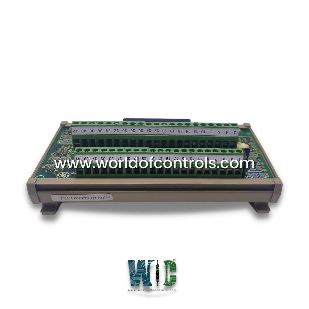
World Of Controls understands the criticality of your requirement and works towards reducing the lead time as much as possible.
IS210DTTCH1A - Simplex Thermocouple Input Board is available in stock which ships the same day.
IS210DTTCH1A - Simplex Thermocouple Input Board comes in UNUSED as well as REBUILT condition.
To avail our best deals for IS210DTTCH1A - Simplex Thermocouple Input Board, contact us and we will get back to you within 24 hours.
Part Number: IS210DTTCH1A
Manufacturer: General Electric
Series: Mark VI
Product Type: Turbine Protection Board
Span: -8 mV to +45 mV
Repair: 3-5 days
Availability: In Stock
Country of Manufacturer: United States (USA)
IS210DTTCH1A is a simplex thermocouple input board developed by General Electric. It is a part of Mark VI control system. The board is a compact terminal board primarily intended for DIN-rail mounting. It boasts 12 thermocouple inputs and establishes connection with the VTCC thermocouple processor board via a single 37-pin cable. Cable mirrors the one utilized by the larger terminal board. The signal conditioning and cold junction reference integrated onto the board align precisely with those featured on the TBTC board. Moreover, an onboard ID chip serves the crucial function of identifying the board to the VTCC, facilitating system diagnostic processes.
WOC has the largest stock of Speedtronic control spares. Please contact our staff by phone or email for pricing and availability on any parts and repairs
What is IS210DTTCH1A?
It is a turbine protection board developed by General Electrics.
How is the thermocouple terminal board connected to the processor board?
The connection between the thermocouple terminal board and the processor board, housing the A/D converter, is established according to a predefined layout. This layout is typically illustrated in a provided figure for reference during installation.
What role does the VTCC play in this setup?
The VTCC provides excitation specifically for the cold junction (CJ) reference present on the thermocouple terminal board. This excitation is crucial for ensuring accurate temperature measurements by compensating for temperature differentials across the thermocouple circuit.
What signals are transmitted through connector JA1?
Connector JA1 serves as the conduit for transmitting various signals between the thermocouple terminal board and the processor board. These signals include the 12 thermocouple signals, the CJ signal for cold junction compensation, and the connection to the identity chip (ID) for system diagnostic purposes.