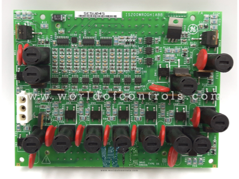
World Of Controls understands the criticality of your requirement and works towards reducing the lead time as much as possible.
IS200WROGH1AAA - Optional Daughter Board is available in stock which ships the same day.
IS200WROGH1AAA - Optional Daughter Board comes in UNUSED as well as REBUILT condition.
To avail our best deals for IS200WROGH1AAA - Optional Daughter Board, contact us and we will get back to you within 24 hours.
Part No.: IS200WROGH1AAA
Manufacturer: General Electric
Country of Manufacture: United States of America (USA)
Trip interlock isolation: Optical isolation to 1500 V
Trip interlock filter: Hardware filter, 4 ms
Size: 17.8 cm wide x 33.02 cm, high
Technology: Surface-mount
Product Type: Optional Daughter Board
Availability: In Stock
Series: Mark VIe
IS200WROGH1AAA is an optional daughter board developed by GE. It is a part of Mark VIe control system. The Mark VIe control system was designed to serve a wide array of control and protection applications, encompassing various sectors and machinery. It is particularly adept at managing and safeguarding steam and gas turbines, which are critical components in power generation. Beyond turbines, the Mark VIe extends its capabilities to the broader balance of plant (BoP) equipment within power generation facilities. This includes auxiliary systems and machinery that support the primary power generation process, ensuring seamless operation and integration of all plant components. By providing a unified control solution, the Mark VIe enhances operational efficiency, reliability, and safety across diverse power generation setups.
The WOC team is always available to help you with your Mark VIe requirements. For more information, please contact WOC.
What is IS200WROGH1AAA?
It is an optional daughter board developed by GE under the Mark VIe series.
What is the RS-232C standard?
It is a protocol for serial communication that specifies the use of 25 signal lines to facilitate data exchange between devices. It defines the electrical characteristics and timing of signals, as well as the meaning of signal voltages.
How many signal lines are used in routine RS-232C communication?
In routine communication, 20 signal lines are used. Additionally, there are two lines for modem testing and three unassigned lines, making up the total of 25 signal lines defined by the standard.
Why are only nine signal pins used in typical RS-232C communication systems?
While the standard specifies 25 signal lines, typical communication systems use only nine signal pins to simplify connections and retain essential functionality. This 9-pin configuration is adequate for most serial communication needs.